5-50
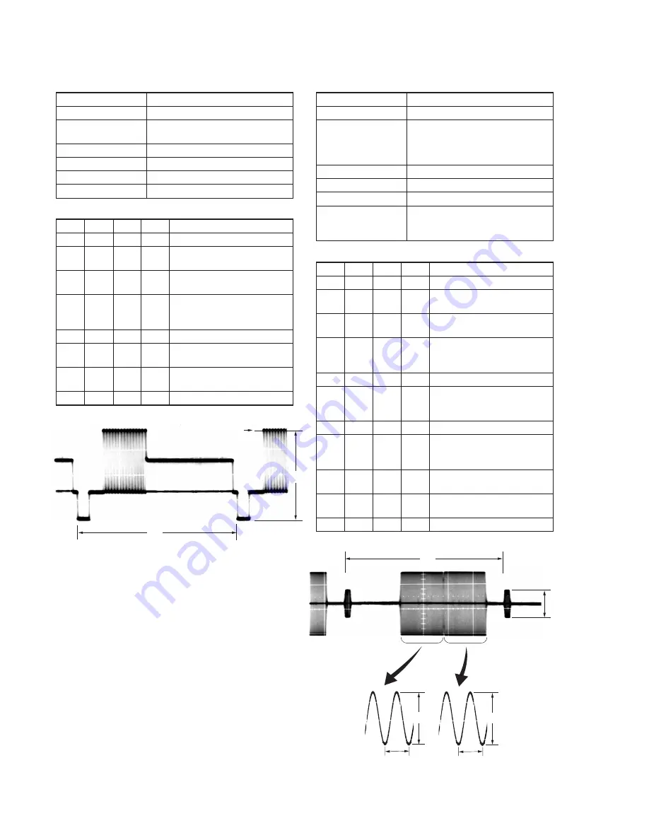
3. S VIDEO OUT Y Level Adjustment (VC-254 board)
Mode
VTR stop
Signal
No signal
Measurement Point
Y signal terminal of S VIDEO OUT
jack (75
Ω
terminated)
Measuring Instrument
Oscilloscope
Adjustment Page
C
Adjustment Address
25
Specified Value
A = 1000 ± 20mV
Adjusting method:
Order Page Address Data
Procedure
1
0
01
01
Set the data.
2
D
11
10
Set the data, and press PAUSE
button.
3
3
0C
02
Set the data, and press PAUSE
button.
4
C
25
Change the data and set the Y
signal level (A) to the specified
value.
5
C
25
Press PAUSE button.
6
3
0C
00
Set the data, and press PAUSE
button.
7
D
11
00
Set the data, and press PAUSE
button.
8
0
01
00
Set the data.
4. S VIDEO OUT Chroma Level Adjustment
(VC-254 board)
Mode
VTR stop
Signal
No signal
Measurement Point
Chroma signal terminal of S VIDEO
OUT jack (75
Ω
terminated)
External trigger: Y signal terminal of
S VIDEO OUT jack
Measuring Instrument
Oscilloscope
Adjustment Page
C
Adjustment Address
26, 27
Specified Value
Cr level:
A = 700 ± 14mV
Cb level:
B = 700 ± 14mV
Burst level: C = 300 ± 6mV
Adjusting method:
Order Page Address Data
Procedure
1
0
01
01
Set the data.
2
D
11
10
Set the data, and press PAUSE
button.
3
3
0C
02
Set the data, and press PAUSE
button.
4
C
26
Change the data and set the Cr
signal level (A) to the specified
value.
5
C
26
Press PAUSE button.
6
C
27
Change the data and set the Cb
signal level (B) to the specified
value.
7
C
27
Press PAUSE button.
8
Check that the burst signal level
(C) is satisfied the specified
value.
9
3
0C
00
Set the data, and press PAUSE
button.
10
D
11
00
Set the data, and press PAUSE
button.
11
0
01
00
Set the data.
Fig. 5-3-10.
Fig. 5-3-11.
H
Center of luminance line
A
H
C
A
0.23
µ
sec
B
0.23
µ
sec
Summary of Contents for Handycam DCR-TRV230E
Page 117: ...DCR TRV230E TRV235E TRV325E TRV330E TRV430E TRV530E 4 69 4 70 USER FUNCTION EVF DRIVE CF 079 ...
Page 119: ...DCR TRV230E TRV235E TRV325E TRV330E TRV430E TRV530E 4 73 4 74 USER FUNCTION EVF DRIVE CF 080 ...
Page 142: ...5 1 DCR TRV230E TRV235E TRV325E TRV330E TRV430E TRV530E SECTION 5 ADJUSTMENTS ...
Page 239: ... Take a copy of OPTICAL AXIS FRAME with a clear sheet for use 304 OPTICAL AXIS FRAME ...


