background image

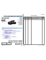
SERVICE MANUAL

SERVICE NOTE (Check the following note before the service.)

Revision History

Published by Sony Techno Create Corporation

Sony Corporation

LEVEL 

2

FDR-AX100/AX100E/HDR-CX900/CX900E_L2

983478532.pdf

Digital 4K Video Camera Recorder: AX100/AX100E

Digital HD Video Camera Recorder: CX900/CX900E

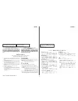
The components identified by mark 

0

 or dotted line with mark 

0

 are 

critical for safety.
Replace only with part number 
specified.

Les composants identifiés par une 
marque 

0

 sont critiques pour la 

sécurité.
Ne les remplacer que par une 
pièce portant le numéro spécifié.

9-834-785-32

Ver.

Date

History

Contents

S.M. Rev.

issued

1.0

2014.03

Official Release

1.1

2014.07

Revised-1
(A1 14-048)

•  Addition of Tourist model in FDR-AX100E.
 Page 

3

Yes

2014G08-1

  © 2014.07

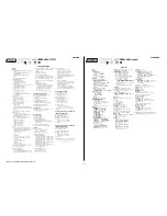
– ENGLISH –

1-1.  

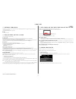
POWER SUPPLY DURING REPAIRS

1-2.  

PRECAUTION ON REPLACING THE VC-1027 BOARD

1-3. 

NOTES FOR REPLACING THE EVF DISPLAY DEVICE (LCD902) OR THE VC-
1027 BOARD

1-4.  

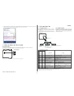
CHECKING THE Wi-Fi FUNCTION

1-5.  

PRECAUTION ON REPLACING THE MS-1022 BOARD

1-6.  

SELF-DIAGNOSIS FUNCTION

1-7.  

METHOD OF COPING WITH SHIFT LENS ERROR

‒ JAPANESE ‒

1-1.  

修理時の電源供給について

1-2.  

VC-1027基板交換時の注意

1-3.  

EVF表示素子(LCD902)またはVC-1027基板交換時の注意

1-4.  

Wi-Fi機能の確認

1-5.  

MS-1022基板交換時の注意

1-6.  

自己診断機能

1-7.  

シフトレンズエラーの対処方法

Ver. 1.1  2014.07

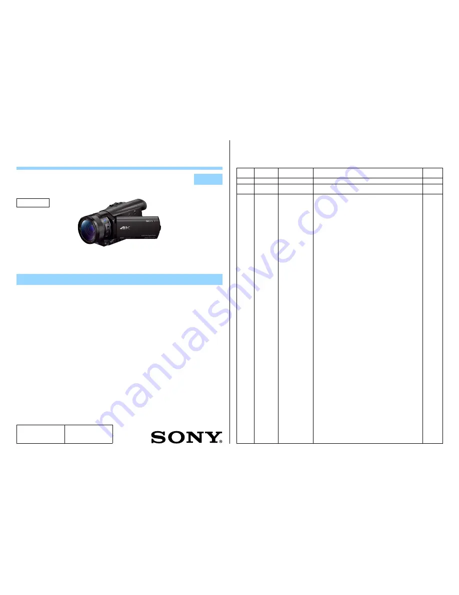
Photo: FDR-AX100

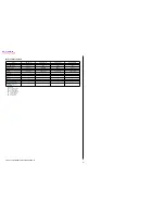
US Model

Canadian Model

AEP Model

E Model

Australian Model

Hong Kong Model

Chinese Model

Korea Model

Tourist Model

Japanese Model

FDR-AX100/AX100E/HDR-CX900/CX900E

Revised-1

Replace the previously issued
SERVICE MANUAL 9-834-785-31
with this Manual.

Summary of Contents for Handycam FDR-AX100

Page 1: ...ease 1 1 2014 07 Revised 1 A1 14 048 Addition of Tourist model in FDR AX100E Page 3 Yes 2014G08 1 2014 07 ENGLISH 1 1 POWER SUPPLY DURING REPAIRS 1 2 PRECAUTION ON REPLACING THE VC 1027 BOARD 1 3 NOTES FOR REPLACING THE EVF DISPLAY DEVICE LCD902 OR THE VC 1027 BOARD 1 4 CHECKING THE Wi Fi FUNCTION 1 5 PRECAUTION ON REPLACING THE MS 1022 BOARD 1 6 SELF DIAGNOSIS FUNCTION 1 7 METHOD OF COPING WITH S...

Page 2: ...the projecting parts the supplied rechargeable battery pack and lens hood attached Mass approx FDR AX100 AX100E 790 g 1 lb 11 oz main unit only 915 g 2 lb including the supplied rechargeable battery pack NP FV70 and lens hood HDR CX900 CX900E 790 g 1 lb 11 oz main unit only 870 g 1 lb 14 oz including the supplied recharge able battery pack NP FV50 and lens hood AC Adaptor AC L200D Power requiremen...

Page 3: ... format 4K HDTV 4K HDTV HDTV HDTV Internal recording media LENS LSV 1730A LSV 1730A LSV 1730A LSV 1730A Projector GPS EVF 3 3 3 3 Wi Fi 3 3 3 3 NFC 3 3 3 3 Multi interface shoe 3 3 3 3 Charging capacitor for flash Abbreviation AUS Australian model CH Chinese model CND Canadian model HK Hong Kong model J Japanese model JE Tourist model KR Korea model The changed portions from Ver 1 0 are shown in b...

Page 4: ... soldering or unsoldering 1 注意事項をお守りください サービスのとき特に注意を要する個所については キャビ ネット シャーシ 部品などにラベルや捺印で注意事項を 表示しています これらの注意書き及び取扱説明書等の注 意事項を必ずお守り下さい 2 指定部品のご使用を セットの部品は難燃性や耐電圧など安全上の特性を持った ものとなっています 従って交換部品は 使用されていた ものと同じ特性の部品を使用して下さい 特に回路図 部 品表に0印で指定されている安全上重要な部品は必ず指定 のものをご使用下さい 3 部品の取付けや配線の引きまわしはもとどおりに 安全上 チューブやテープなどの絶縁材料を使用したり プリント基板から浮かして取付けた部品があります また 内部配線は引きまわしやクランパによって発熱部品や高圧 部品に接近しないよう配慮されていますので これらは必 ずも...

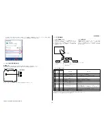
Page 5: ... on the ADJUST tab If Wireless LAN Setting MAC Address is not executed and the backup data before replacement is restored the MAC address in the Wi Fi module does not match the MAC address in the flash memory causing an error during Wi Fi transfer Note The LOAD AND WRITE function in ADJUSTMENT DATA BACKUP on the DATA tab in the Adjust manual overwrites all data of the unit Therefore the MAC addres...

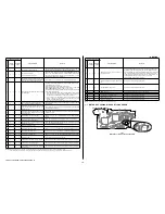
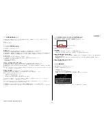
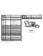
Page 6: ... the repaired by block in which the problem occurred and detailed code of the problem 0 0 3 2 C Repaired by Refer to 1 6 3 Self diagnosis Code Table Indicates the appropriate step to be taken E g 13 32 Turn on power again Block Detailed Code Blinks at 3 2 Hz C Corrected by customer E Corrected by service engineer Format the memory card Viewfinder or LCD screen 1 6 3 Self diagnosis Code Table Self ...

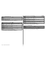
Page 7: ...ircuit IC1802 on the VC 1027 board E 6 2 0 4 Image vibration correction during handshake function does not work Inspect the image vibration angular velocity sensors SE7711 on the VC 1027 board peripheral circuits E 6 2 1 0 Shift lens initializing failure Replacement of lens block Note 3 If an error occurs again replace the VC 1027 board E 6 2 1 1 Shift lens overheating Pitch Refer to 1 7 2 E 62 11...

Page 8: ... periphery Note When the lens block was replaced start the Adjust Manual in the Adjust Station and execute the necessary adjustment items After the adjustment make sure with the STEADYSHOT turned ON that the steadyshot functions appropriately in the handheld operation 1 7 3 E 62 12 Shift Lens Overheating Yaw Occurred Order Procedure 1 Start the Adjust Manual in the Adjust Station and execute the M...

Page 9: ...nualをダウンロードする 2 ダウンロードしたAdjust manualをインストールする 3 ADJUSTタブにある Wireless LAN Setting MAC Address を実行する これを実行せずに交換前のバックアップデータを書き戻すと Wi Fiモジュール内のMACアドレスとフラッシュメモリー内の MACアドレスが不一致となり Wi Fi転送時にエラーとなります Note Adjust manual内のDATAタブにある ADJUSTMENT DATA BACKUP の機能 LOAD AND WRITE は セッ トの全てのデータを上書きします その ため 上記の操作で更新したMACアドレスも上書きされてしまいます 交換修理後はMACアドレスが変更されていますので お客様に接続機器の再設定をしていただく必要があります そのためFlyer of WLAN Reset Fl...

Page 10: ...の表示によって対 応者分類および不具合の生じたブロックの分類 不具合の詳細 コードを示します 0 0 C 2 3 対応者分類 1 6 3 自己診断コード表 を参照 対応方法の違いにより分類 例 メモリーカードをフォーマットする 3 1 32 電源を入れ直す ブロック分類 詳細コード 3 2 Hz点滅 C お客さま自身で対応 E サービスエンジニア で対応 ビューファインダーまたはLCD画面 1 6 3 自己診断コード表 自己診断コード 症状 状態 対応 方法 対 応 者 ブロック 機能 詳細 コード C 0 4 0 0 標準以外のバッテリを使用している インフォリチウムバッテリを使用する C 0 6 0 0 バッテリが高温になっている バッテリを交換するか バッテリを涼しいとこに置く C 1 3 0 1 フォーマットしていないメモリーカード を入れた メモリーカードが壊れている メモリーカ...

Page 11: ... 1027基板IC1802 を点検 E 6 2 0 4 Active手振れ補正時の画ゆれが補正 できない 角速度センサ出力張り付き 画ゆれ検出角速度センサ VC 1027基板SE7711 周辺回路を点検する E 6 2 1 0 シフトレンズ初期化異常 レンズブロックを交換する Note 3 エラーが再度発生する場合は VC 1027基板を交換する E 6 2 1 1 シフトレンズオーバーヒート PITCH 1 7 2 E 62 11 シフトレンズオーバーヒート PITCH が出た場合 を参照 E 6 2 1 2 シフトレンズオーバーヒート YAW 1 7 3 E 62 12 シフトレンズオーバーヒート YAW が出た場合 を参照 E 6 2 2 0 サーミスタの異常 1 7 4 E 62 20 サーミスタの異常 が出た場合 を参照 E 6 2 3 0 CPU異常 電源を入れ直す E 9 1...

Page 12: ...上がらない場合はVC 1027基板のIC6000とIC1802の回路周辺を点検する 注意 レンズブロックを交換した場合は Adjust StationからAdjust Manualを起動させて必要な調整項目を実施するこ と 調整後は手ぶれ補正ONの状態にして 手持ち動作で手ぶれ補正が適正に効いているこ とを確認するこ と 1 7 3 E 62 12 シフトレンズオーバーヒート Yaw が出た場合 順序 作業内容 1 Adjust StationからAdjust Manualを起動させて SERVICE タブにある Measure to E 62 11 12 を実施する 2 順序1を実行した後にシフトレンズが動いているか確認する もしシフトレンズが動かない場合はレンズブロックを交換する 注意 動く場合は順序3に進む 3 VC 1027基板のIC1802周辺にあるC1820とC1822の出力電...

Page 13: ...loded views are not supplied Due to standardization replacements in the parts list may be different from the parts specified in the diagrams or the components used on the set CAPACITORS uF μF COILS uH μH RESISTORS All resistors are in ohms METAL metal film resistor METAL OXIDE Metal Oxide film resistor F nonflammable SEMICONDUCTORS In each case u μ for example uA μA uPA μPA uPB μPB μPC μPC uPD μPD...

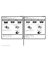
Page 14: ...t reaches the end inside Fig 1 Fig 2 Fig 3 OK The flexible board was plugged in straight and completely NG The flexible board was plugged in crooked NG The flexible board was not plugged in completely Flexible Board Flexible Board Connector Connector Reference line Flexible Board Connector Connector Flexible Board Reference line Connector Connector Flexible Board Flexible Board Reference line Fig ...

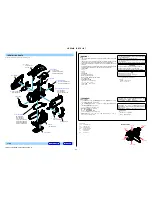
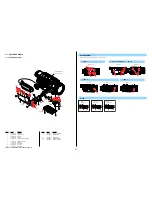
Page 15: ...2 589 376 01 FOOT 395 RUBBER 12 4 533 029 01 CABINET BM 2 2 635 562 31 SCREW M1 7 11 3 078 890 11 SCREW TAPPING 12 3 080 204 21 SCREW TAPPING P2 1 Remove in numerical order 1 to 5 in the left figure DISASSEMBLY 1 2 X 7 Screw Bottom View 2 2 2 2 M1 7 X 4 0 Black 2 635 562 31 4 0 1 7 11 M1 7 X 4 0 Tapping Silver 3 078 890 11 4 0 1 7 12 M1 7 X 5 0 Tapping Black 3 080 204 21 1 7 5 0 2 Open the USB Lid...

Page 16: ...562 31 SCREW M1 7 11 3 078 890 11 SCREW TAPPING 124 2 599 475 01 SCREW M1 7 1 Remove in numerical order 1 to 6 in the left figure DISASSEMBLY 1 2 X 2 Right View Back View 2 2 3 Open the Shoe Cover 3 1 2 X 8 Slide the View finder 3 2 and disengage the claws Top View Left View Right View 2 2 Claws Claws 2 2 3 1 3 2 4 2 X 8 6 Open the Lids 6 1 6 2 2 X 3 Top View 2 2 2 2 6 1 6 2 Right View 2 Bottom Vi...

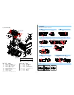
Page 17: ...Note 1 2 2 635 562 31 SCREW M1 7 12 3 080 204 21 SCREW TAPPING P2 1 Remove in numerical order 1 to 8 in the left figure DISASSEMBLY 1 12 X 2 2 X 2 2 2 X 6 Screw Note Top View Left View Right View 12 2 2 Left View Bottom View Back View 2 2 2 2 2 1 6 5 3 4 7 8 2 A A B B 101 102 103 106 105 108 109 110 111 113 114 115 116 117 112 104 107 2 2 2 2 2 ns 2 2 2 12 2 2 2 2 2 2 2 BT4301 Note 1 Note 1 BH4301...

Page 18: ... 3 2 X 1 Top View Right View Bottom View Left View 2 2 12 12 12 2 12 12 Note Note 1 Use this to cut or splice so that it become the designated size Note 1 指定のサイズになるように形状を加工して使用してくださ い Note 2 Refer to Assembly 1 Notes on Assembling the Heat Sink T Note 2 Assembly 1 Notes on Assembling the Heat Sink T を参 照してください 151 152 154 156 157 157 160 155 153 158 2 12 12 Note 1 Size 12 X 12 mm Note 2 Note 3 Not...

Page 19: ...CABINET R CX900 CX900E 213 4 532 972 11 CABINET R AX100 AX100E 214 2 589 376 01 FOOT 395 RUBBER 215 4 532 981 01 LID HP 216 4 537 511 01 GASKET R SP901 1 858 528 51 SPEAKER 2 1CM 11 3 078 890 11 SCREW TAPPING 124 2 599 475 01 SCREW M1 7 288 2 187 345 21 SCREW M1 7 P2 Note 1 Note Note 1 This screw cannot be reused Discard the screw removed once in servicing Instead use a new screw Note 1 このねじは再利用する...

Page 20: ... X 2585 819 1 HINGE Y 409 ASSY T TYPE 265 1 487 270 11 BLOCK LIGHT GUIDE PLATE 3 5 266 3 079 115 01 TAPE AS LCD901 1 811 403 11 LCD WITH TOUCH PANEL 11 3 078 890 11 SCREW TAPPING 267 4 287 436 21 SCREW M1 7 288 2 187 345 21 SCREW M1 7 P2 Note 1 Screw 2 1 6 LCD BLOCK SECTION Note Note 3 Refer to Assembly 2 The Method of attachment of FP 2212 Flexible Board Note 3 Assembly 2 The Method of attachment...

Page 21: ...2 405 A SERVICE ORNAMENT BLOCK ASSY 314 4 532 996 01 SHEET LENS RING ADHESIVE Ref No Part No Description Ref No Part No Description 315 4 532 998 01 ORNAMENT MICROPHONE 316 4 532 997 01 GRILLE MICROPHONE 317 4 532 999 01 SCREEN WIND 318 4 533 000 01 MOLD MICROPHONE INNER 319 4 534 920 01 INSULATOR 470 MICROPHONE 320 4 533 001 01 FRAME MICROPHONE 321 4 532 995 01 RING L ORNAMENTAL 322 4 451 056 01 ...

Page 22: ... METAL R GRIP BELT 370 4 422 339 01 GUARD BELT 371 1 838 712 51 CABLE BUILT IN USB 372 X 2584 854 1 BELT G ASSY 12 TYPE GRIP 373 2 589 376 01 FOOT 395 RUBBER J901 1 842 658 51 JACK DC 2 2 635 562 31 SCREW M1 7 12 3 080 204 21 SCREW TAPPING P2 288 2 187 345 21 SCREW M1 7 P2 Note 1 2 1 8 BT SECTION Screw Note Note 1 This screw cannot be reused Discard the screw removed once in servicing Instead use ...

Page 23: ...11 01 DIAL DIOPTER 416 A 2035 841 A FP 2202 FLEXIBLE BOARD COMPLETE 417 4 533 012 01 HOLDER VF LCD902 A 2047 084 A ECX333AA 1 SERVICE Note 3 12 3 080 204 21 SCREW TAPPING P2 2 1 9 EVF SECTION Screw Note 12 12 12 12 12 12 Note 3 12 LCD902 401 402 408 409 410 411 413 414 415 416 412 417 403 404 405 406 407 Note 2 Size 7 7 x 7 7 mm Note 2 Size 12 x 12 mm 12 M1 7 X 5 0 Tapping Black 3 080 204 21 1 7 5...

Page 24: ...0 204 21 SCREW TAPPING P2 Ref No Part No Description 2 1 10 LENS SECTION ns not supplied Screw Note 455 including CM 1010 complete board CP2001 CMOS imager 12 ns ns ns ns ns ns ns Note ns Note ns 12 12 12 12 12 12 12 451 454 452 453 452 12 M1 7 X 5 0 Tapping Black 3 080 204 21 1 7 5 0 Note If this parts are disassembled reassemble them correctly Do not lose the adjustment washer The adjustment was...

Page 25: ...9 4 534 651 31 Operating Guide SPANISH 909 4 534 651 41 Operating Guide TRADITIONAL CHINESE 909 4 534 652 01 Operating Guide JAPANESE 909 4 534 652 11 Operating Guide KOREAN 909 4 534 653 11 Operating Guide GERMAN DUTCH ITALIAN PORTUGUESE CZECH SLOVAK 909 4 534 653 21 Operating Guide POLISH HUNGARIAN SWEDISH DANISH FINNISH 909 4 534 653 31 Operating Guide RUSSIAN 909 4 534 653 41 Operating Guide U...

Page 26: ... 1 490 430 22 ACアダプター 952 1 836 251 11 電源コード 953 1 838 714 31 USB接続サポートケーブル 954 1 846 028 11 HDMIケーブル 955 X 2589 702 1 レンズフード 956 1 479 275 51 ワイヤレスリモコン 957 X 2588 286 3 レンズキャップ 958 4 534 652 01 取扱説明書 Ref No Part No Description 8 022 175 00 リチャージャブルバッテリーパッ クNP FV50 J CX900 8 022 176 00 リチャージャブルバッテリーパッ クNP FV70 J AX100 ...

Page 27: ...e Method of attachment of FP 2212 Flexible Board 1 Fold dotted line parts of the FP 2212 Flexible Board as shown in figure Adhesive tape Adhesive tape Adhesive tape Valley fold Mountain fold 2 Roll the FP 2212 Flexible Board 2 times in the Hinge Assy as shown in figure 2 Times Flexible Board Hinge Assy 3 Install the Hinge Cover U Hinge Cover O Hinge Cover U Hinge Cover O ...

Page 28: ...be sure to confirm the contents of them Note 1 Be sure to install Adjust station first Note 2 To perform Destination Data Write for this model the Adjust manual of the DSC WX50 series must have been installed Install the Adjust manual of the DSC WX50 series in advance JAPANESE これらの機種で調整を行なうには アジャストマニュアルとアジャストステーションが必要です アジャストステーションとは 機種別のアジャストマニュアルを起動するためのソフトウェアです アジャストステーションのインストーラと一緒に インストレーションマ...

Reviews: