background image

HAP-S1

HAP-S1

47

47

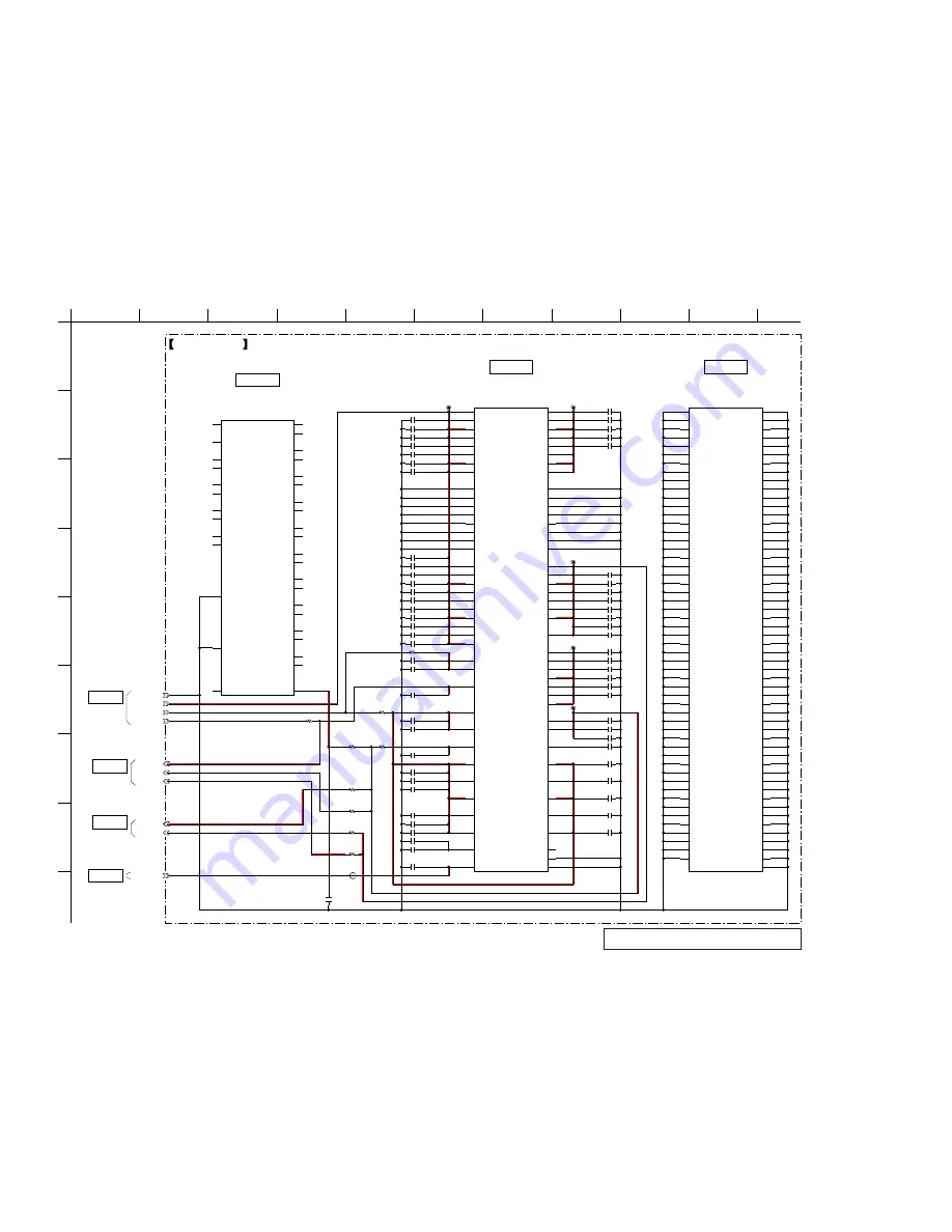
5-7.  SCHEMATIC  DIAGRAM - MAIN Section (1/9) -

• See page 86 for IC Pin Function Description.

Note: 

IC101 on the MAIN board cannot exchange with single. When 
this part is damaged, exchange the complete mounted board.

0.22

C153

0.22

C154

0.22

C155

0.22

C156

0.22

C127

0.22

C126

0.22

C125

0.22

C128

0.22

C152

0.22

C124

0.22

C123

0.22

C121

0.22

C159

0.22

C120

0.22

C150

0.22

C144

0.22

C145

0.22

C157

0.22

C146

0.22

C147

0.22

C148

0.22

C129

0.22

C130

0.22

C131

0.22

C132

0.22

C137

0.22

C138

0.22

C139

0.22

C140

0.22

C141

0.22

C142

0.22

C102

0.22

C103

0.22

C104

0.22

C105

0.22

C106

0.22

C111

0.22

C112

0.22

C113

0.22

C114

0.22

C115

0.22

C116

0.22

C117

0.22

C118

0.22

C119

SATA_1.1V

PCIE_1.1V

SATA_2.5V

PCIE_2.5V

0.22

C151

1.42V

CL101

CL102

CL103

CL104

0

R104

0

R103

0

R116

0

R108

0

R109

0

R105

0

R106

R117

0

0.22

C101

CL105

22

C180

22

C182

22

C183

22

C184

22

C193

22

C192

22

C185

22

C186

22

C187

22

C188

3.3V

STANDBY3.3V

GND

SNVS3.3V

10

C189

10

C194

FB101

0.01

C174

MCIMX6D5EYM10AC

IC101

VDDARM_IN1

H14

VDDARM_IN2

J14

VDDARM_IN3

K14

VDDARM_IN4

L14

VDDARM_IN5

M14

VDDARM_IN6

N14

VDDARM_IN7

P14

VDDARM_IN8

R14

VDDARM23_IN1

K9

VDDARM23_IN2

L9

VDDARM23_IN3

M9

VDDARM23_IN4

N9

VDDARM23_IN5

P9

VDDARM23_IN6

R9

VDDARM23_IN7

T9

VDDARM23_IN8

U9

VDDSOC_IN1

H16

VDDSOC_IN2

J16

VDDSOC_IN3

K16

VDDSOC_IN4

L16

VDDSOC_IN5

M16

VDDSOC_IN6

N16

VDDSOC_IN7

P16

VDDSOC_IN8

R16

VDDSOC_IN9

T16

VDDSOC_IN10

U16

VDDHIGH_IN1

H9

VDDHIGH_IN2

J9

VDD_SNVS_IN

G11

NVCC_LCD

P19

NVCC_CSI

N7

NVCC_MIPI

K7

NVCC_EIM0

K19

NVCC_EIM1

L19

NVCC_EIM2

M19

NVCC_ENET

R19

NVCC_GPIO

P7

NVCC_PLL_OUT

E8

NVCC_RGMII

G18

VDDARM_CAP_1 H13

VDDARM_CAP_2 J13

VDDARM_CAP_3 K13

VDDARM_CAP_4 L13

VDDARM_CAP_5 M13

VDDARM_CAP_6 N13

VDDARM_CAP_7 P13

VDDARM_CAP_8 R13

VDDARM23_CAP_1 H11

VDDARM23_CAP_2 J11

VDDARM23_CAP_3 K11

VDDARM23_CAP_4 L11

VDDARM23_CAP_5 M11

VDDARM23_CAP_6 N11

VDDARM23_CAP_7 P11

VDDARM23_CAP_8 R11

VDDSOC_CAP_1 R10

VDDSOC_CAP_2 T10

VDDSOC_CAP_3 T13

VDDSOC_CAP_4 T14

VDDSOC_CAP_5 U10

VDDSOC_CAP_6 U13

VDDSOC_CAP_7 U14

VDD_CACHE_CAP N12

VDDPU_CAP_1 H17

VDDPU_CAP_2 J17

VDDPU_CAP_3 K17

VDDPU_CAP_4 L17

VDDPU_CAP_5 M17

VDDPU_CAP_6 N17

VDDPU_CAP_7 P17

VDDHIGH_CAP_1 H10

VDDHIGH_CAP_2 J10

VDD_SNVS_CAP G9

NVCC_SD1 G16

NVCC_SD2 G17

NVCC_SD3 G14

NVCC_NANDF G15

NVCC_JTAG J7

GPANAIO C8

FA_ANA A5

VDD_FA B5

MCIMX6D5EYM10AC

IC101

GND1

A13

GND2

A25

GND3

A4

GND4

A8

GND5

AA10

GND6

AA13

GND7

AA16

GND8

AA19

GND9

AA22

GND10

AA7

GND11

AB24

GND12

AB3

GND13

AD10

GND14

AD13

GND15

AD16

GND16

AD19

GND17

AD22

GND18

AD4

GND19

AD7

GND20

AE1

GND21

AE25

GND22

B4

GND23

C1

GND24

C10

GND25

C4

GND26

C6

GND27

D3

GND28

D6

GND29

D8

GND30

E5

GND31

E6

GND32

E7

GND33

F5

GND34

F6

GND35

F7

GND36

F8

GND37

G10

GND38

G19

GND39

G3

GND40

H12

GND41

H15

GND42

H18

GND43

H8

GND44

J12

GND45

J15

GND46

J18

GND47

J2

GND48

J8

GND49

K10

GND50

K12

GND51

K15

GND52

K18

GND53

K8

GND54

L10

GND55

L12

GND56

L15

GND57

L18

GND58

L2

GND59

L5

GND60

L8

GND61

M10

GND62

M12

GND63

M15

GND64

M18

GND65

M8

GND66

N10

GND67

N15

GND68

N18

GND69

N8

GND70

P10

GND71

P12

GND72

P15

GND73

P18

GND74

P8

GND75

R12

GND76

R15

GND77

R17

GND78

R8

GND79

T11

GND80

T12

GND81

T15

GND82

T17

GND83

T19

GND84

T8

GND85

U11

GND86

U12

GND87

U15

GND88

U17

GND89

U8

GND90

U19

GND91

V8

GND92

V19

GND93

W3

GND94

W7

GND95

W8

GND96

W9

GND97

W10

GND98

W11

GND99

W12

GND100

W13

GND101

W15

GND102

W16

GND103

W17

GND104

W18

GND105

W19

GND106

Y5

GND107

Y24

ETHER_1.8V

22

C190

0

R901

0.1

C901

MCIMX6D5EYM10AC

HDMI_HPD

K1

HDMI_DDCCEC

K2

HDMI_CLKM

J5

HDMI_CLKP

J6

HDMI_D0M

K5

HDMI_D0P

K6

HDMI_D1M

J3

HDMI_D1P

J4

HDMI_D2M

K3

HDMI_D2P

K4

HDMI_VP

L7

HDMI_VPH

M7

HDMI_REF

J1

LVDS0_TX0_N

U2

LVDS0_TX0_P

U1

LVDS0_TX1_N

U4

LVDS0_TX1_P

U3

LVDS0_TX2_N

V2

LVDS0_TX2_P

V1

LVDS0_CLK_N

V4

LVDS0_CLK_P

V3

LVDS0_TX3_N

W2

LVDS0_TX3_P

W1

LVDS1_TX0_N

Y1

LVDS1_TX0_P

Y2

LVDS1_TX1_N

AA2

LVDS1_TX1_P

AA1

LVDS1_TX2_N

AB1

LVDS1_TX2_P

AB2

LVDS1_CLK_N

Y3

LVDS1_CLK_P

Y4

LVDS1_TX3_N

AA3

LVDS1_TX3_P

AA4

NVCC_LVDS2P5

V7

(1/10)
IC101

MPU

CSP

(Chip Size Package)

(2/10)
IC101

MPU

CSP

(Chip Size Package)

(3/10)
IC101

MPU

CSP

(Chip Size Package)

IC101

>101S

MAIN

(2/9)

BOARD

>102S

MAIN

(4/9)

BOARD

>103S

MAIN

(9/9)

BOARD

>104S

MAIN

(6/9)

BOARD

D

E

G

H

I

F

2

B

3

A

4

5

1

6

7

8

9

10

11

C

(1/9)

MAIN BOARD

(Page 52)

(Page 55)

(Page 50)

(Page 48)

Summary of Contents for HAP-S1

Page 1: ... OPTICAL IN Supported playback format LPCM 2ch Sampling frequency 44 1 kHz 48 kHz 88 2 kHz 96 kHz Quantization bits 16 bits 24 bits LINE IN 1 2 Input sensitivity 500 mV Input impedance 100 kilohms Output section Output jacks LINE OUT Output impedance 2 2 kilohms 2 Hz 80 kHz 3 dB PHONES headphone jack Stereo jack 8 ohms or higher EXT port Type A USB Hi Speed USB for connecting an external hard disk...

Page 2: ...C3 ATRAC3plus ATRAC Advanced Lossless and their logos are trademarks of Sony Corporation 12 TONE ANALYSIS and its logo are trademarks of Sony Corporation DSEE is a registered trademark of Sony Corporation SensMe and the SensMe logo are trademarks or registered trademarks of Sony Ericsson Mobile Communications AB Microsoft Windows Windows Vista and Windows Media are either trademarks or registered ...

Page 3: ...n 3 9 49 5 10 Schematic Diagram MAIN Section 4 9 50 5 11 Schematic Diagram MAIN Section 5 9 51 5 12 Schematic Diagram MAIN Section 6 9 52 5 13 Schematic Diagram MAIN Section 7 9 53 5 14 Schematic Diagram MAIN Section 8 9 54 5 15 Schematic Diagram MAIN Section 9 9 55 5 16 Printed Wiring Board DIGITAL IO Board 56 5 17 Schematic Diagram DIGITAL IO Board 57 5 18 Printed Wiring Board FPGA DSP Board 58 ...

Page 4: ...ear side of a main unit Rear Panel PART No Destination Part No US and Canadian models 4 464 753 1 AEP and UK models 4 464 753 2 NOTE OF REPLACING THE D218 IC350 AND IC351 ON THE AMP BOARD AND THE COMPLETE AMP BOARD When D218 IC350 and IC351 on theAMP board and the complete AMP board are replaced it is necessary to spread the compound between these parts and the heat sink Spread the compound TB2955...

Page 5: ...n changed when returning the unit to the customer print and cut out the following explana tion and hand it over with the unit The MAC address for the wireless LAN has been changed by this repair Customers who use the MAC address filtering function of the connected access point equipment should set it again Note There are two kinds of MAC addresses wired and wireless Only wireless MAC addresses are...

Page 6: ...HAP S1 6 MAIN BOARD SERVICE POSITION DCDC BOARD SERVICE POSITION insulation stand MAIN board front panel block U COM board insulation DCDC board front panel block ...

Page 7: ...R KEY BOARD Page 11 2 6 LCD HOLDER BLOCK Page 12 2 7 LCD PANEL LCD1 Page 12 2 13 ALLEGRO ANT R BOARD Page 16 2 8 WLAN BT COMBO CARD WBC1 Page 13 2 9 CLAMP FILTER FERRITE CORE FC1 FC2 Page 14 2 14 CLAMP FILTER FERRITE CORE FC4 Page 17 2 15 DCDC BOARD 1 Page 18 2 16 DCDC BOARD 2 Page 19 2 17 WIRE HOLDER Page 20 2 10 FERRITE CORE FC3 Page 14 2 11 HDD HDD1 Page 15 2 12 ANT HOLDER BLOCK RIGHT SIDE Page...

Page 8: ...ME BLOCK WIRES Page 21 2 20 U COM BOARD Page 22 2 24 ANT HOLDER BLOCK LEFT SIDE Page 24 2 25 ALLEGRO ANT L BOARD Page 25 2 26 BRACKET DCDC F Page 26 2 34 DAC BOARD Page 30 2 32 AC INLET 2P AC1 Page 29 2 33 STANBY BOARD Page 30 2 27 DIGITAL IO BOARD Page 26 2 28 AMP BOARD 1 Page 27 2 29 AMP BOARD 2 Page 28 2 31 SPTM BOARD Page 29 2 30 HEAT SINK ALG Page 28 ...

Page 9: ...ide panel L assy in the direction of an arrow 4 Remove the side panel R assy in the direction of an arrow 6 side panel L assy 6 side panel R assy 5 two claws 5 two claws 5 claw 5 claw 1 flat screw 1 flat screw 3 hook 3 hook 2 Insert a tweezers etc to hole of chassis and slide the hook in the direction of the arrow Note Please spread a sheet under a unit not to panel ...

Page 10: ...plates AL are not damaged and being installed Rear bottom view Rear view ire VettiQJ 4 Remove the front panel ALG block in the direction of an arrow 5 Remove the front panel ALG block in the direction of an arrow 9 front panel ALG block 6 flexible flat cable 17P CN5010 7 flexible flat cable 40P CN001 8 connector CN2001 Note 2 When installing the flexible flat cable ensure the colored line No slant...

Page 11: ...LG block rear bottom view 2 Remove the HP board block in the direction of an arrow 5 HP board 1 two screws BVTP2 6 3 connector CN1002 Front panel ALG block rear bottom view 2 Remove the POWER KEY board block in the direction of an arrow 4 POWER KEY board POWER KEY board KEY JOG board ALLEGRO LCD board ire VettinJ ...

Page 12: ...tom view 2 LCD holder block Rear bottom view 1 LCD flexible board CN002 5 LCD panel LCD1 LCD panel LCD1 3 LCD cushion A LCD cushion A 2 Peel off the A adhesive 4 LCD cushion B LCD cushion B bottom side top side Note Attach to fit the corner Note Attach to fit the corner ttaFKeG SoVitioQ oI FXVKioQ ...

Page 13: ...or C2 black coaxial cable U FL connector C2 black saranet cushion saranet cushion DCDC board saranet cushion 1 two saranet cushions 2 screw BV3 3 flat screw LUH VHWWLQJ LUH VHWWLQJ 4 Remove the WLAN BT COMBO card block in the direction of an arrow qd WLAN BT COMBO card WBC1 WLAN BT COMBO card WBC1 qs cover RF RWWRP YLHZ Note When the WLAN BT COMBO card Ref No WBC1 is replaced refer to CHECKING MET...

Page 14: ...same as before LUH VHWWLQJ 5 clamp filter ferrite core FC2 1 saranet cushion 1 saranet cushion saranet cushion 2 two hooks LUH VHWWLQJ 3 flexible flat cable 24P CN001 flexible flat cable 24P DIGITAL IO board 4 ferrite core FC3 colored line connector flexible flat cable Note When installing the flexible flat cable ensure the colored line No slanting after insertion saranet cushion LUH VHWWLQJ flexi...

Page 15: ... 5 Note 2 No problem using the electric screwdriver when installing or removing these screws When tightening screws tighten the below torque value tightening torque N m HDD HDD1 DCDC board LUH VHWWLQJ 1 flat screw 2 Remove the ANT holder block right side in the direction of an arrow 4 ANT holder block right side 3 three claws Note 1 When the hard disk drive Ref No HDD1 is replaced refer to NOTE OF...

Page 16: ...CN9002 coaxial cable U FL connector WR2 coaxial cable U FL connector WR2 6 two claws 8 ANT holder 7 Remove the ALLEGRO ANT R board block in the direction of an arrow 9 ALLEGRO ANT R board LUH VHWWLQJ LUH VHWWLQJ ANT shield R ALLEGRO ANT R board ANT holder start point tape WA L end point sheet WA L No gap start point end point WWDFKHG SRVLWLRQ RI WKH VKHHW DQG WKH WDSH Note The ALLEGRO ANT R board ...

Page 17: ...E CORE FC4 1 Remove wires from three lead pins lead pin lead pin lead pin 2 connector CN4003 3 clamp filter ferrite core FC4 clamp filter ferrite core FC4 DIGITAL IO board LUH VHWWLQJ DIGITAL IO board DCDC board wire holder LUH VHWWLQJ ...

Page 18: ...RD 1 1 Remove wires from three lead pins 2 connector CN4005 4 connector CN4008 5 connector CN4009 3 connector CN4013 LUH VHWWLQJ DIGITAL IO board lead pin lead pin lead pin LUH VHWWLQJ DIGITAL IO board DCDC board wire holder ...

Page 19: ...clamp filter ferrite core FC5 3 connector CN2408 4 three screws BV3 5 Remove the DCDC board block in the direction of an arrow DCDC board power transformer T1 6 saranet cushion 7 sleeve ferrite clamp FC6 sleeve ferrite clamp FC6 0 connector CN2406 qs DCDC board DCDC board lead pin qa connector CN2407 8 connector CN2402 9 connector CN2403 RWWRP YLHZ ...

Page 20: ...aw 3 Remove the wire holder in the direction of an arrow 5 wire holder 1 three claws 7 Draw out the wire 2 shield plate FFC 3 flat screw 4 claw 3 flat screw 8 connector CN215 3 flat screw 3 flat screw 4 claw 6 claw 6 claw 5 Remove the sub frame block in the direction of an arrow 9 sub frame block ...

Page 21: ...le 24P CN4006 3 Remove wires from the clamp 4 Remove wires from two lead pins 5 connector CN203 6 connector CN701 7 connector CN201 8 connector CN5002 9 connector CN5003 0 connector CN5008 qa connector CN5005 qs harness E 001 WR4 CN601 qd harness S 001 WR5 CN1001 lead pin lead pin FPGA DSP board MAIN board clamp LUH VHWWLQJ LUH VHWWLQJ LUH VHWWLQJ MAIN board U COM board 5HDU YLHZ saranet cushion s...

Page 22: ...HAP S1 22 2 20 U COM BOARD 2 21 FPGA DSP BOARD 1 three screws BV3 2 U COM board 1 two screws BV3 1 two screws BV3 2 connector CN402 3 FPGA DSP board ...

Page 23: ...C R Note In reassembling use new cable tie to fasten the clamp same as before 3 Remove the wire from the clamp clamp 5 clamp filter ferrite core FC7 clamp filter ferrite core FC7 6 two screws BV sumitite S 4 u 6 round 6 screw BV sumitite S 4 u 6 round 7 power transformer T1 power transformer T1 AMP board 6 screw BV sumitite S 4 u 6 round LUH VHWWLQJ Note When the complete MAIN board is replaced re...

Page 24: ...HAP S1 24 2 24 ANT HOLDER BLOCK LEFT SIDE 1 flat screw 2 Remove the ANT holder block left side in the direction of an arrow 4 ANT holder block left side 3 three claws ...

Page 25: ...U FL connector WR1 CN9001 coaxial cable U FL connector WR1 coaxial cable U FL connector WR1 6 two claws 8 ANT holder 7 Remove the ALLEGRO ANT L board block in the direction of an arrow 9 ALLEGRO ANT L board LUH VHWWLQJ ANT shield L ALLEGRO ANT L board ANT holder start point tape WA L end point sheet WA L No gap start point end point WWDFKHG SRVLWLRQ RI WKH VKHHW DQG WKH WDSH Note The ALLEGRO ANT L...

Page 26: ...e 1 screw BV3 1 screw BV3 3 connector CN202 5 sleeve ferrite clamp FC8 LUH VHWWLQJ 20 5 mm sleeve ferrite clamp FC8 3 two screws BV3 4 screw BV3 4 screw BV3 5 Remove the DIGITAL IO board block in the direction of an arrow 7 DIGITAL IO board 6 cushion digital 1 flexible flat cable 22P CN4007 2 connector CN4010 colored line connector flexible flat cable Note When installing the flexible flat cable e...

Page 27: ...V3 3 Remove wires from two lead pins lead pin lead pin 3 Remove wires from three lead pins 4 Remove wires from the clamp 2 bracket DIGITAL lead pin lead pin lead pin lead pin clamp lead pin DAC board STANBY board STANBY board SPTM board AMP board LUH VHWWLQJ sleeve ferrite clamp FC9 3 8 86 DQDGLDQ LUH VHWWLQJ A ...

Page 28: ...ock in the direction of an arrow 8 AMP board 1 screw BV3 1 screw BV3 4 two screws transistor 2 clamp 2 clamp 3 bracket DCDC R AEP UK 1 three screws BV3 2 heat sink ALG Note When the complete AMP board is replaced refer to NOTE OF REPLACING THE D218 IC350 AND IC351 ON THE AMP BOARD AND THE COMPLETE AMP BOARD on page 4 ...

Page 29: ...row 4 SPTM board 3 four canoe clips 4 two screws BV3 5 AC inlet 2P AC1 1 connector CN1903 2 Cut the cable tie cable tie cable tie Note In reassembling use new cable tie to fasten the clamp same as before 2 Cut the cable tie 3 clamp filter ferrite core FC10 clamp filter ferrite core FC10 STANBY board AC inlet 2P AC1 LUH VHWWLQJ ...

Page 30: ...2 two screws BV3 lead pin 2 two screws BV3 3 Remove the DCDC board block in the direction of an arrow 4 saranet cushion saranet cushion ferrite core FC11 DAC board 5 flexible flat cable 22P CN402 flexible flat cable 22P 7 connector CN401 8 DAC board 6 ferrite core FC11 colored line connector flexible flat cable Note When installing the flexible flat cable ensure the colored line No slanting after ...

Page 31: ... Releasing Method of The Service DIAG Mode Press the 1 button Except the state of 3 3 KEY Check 5 5 SMART Short Test and 5 6 SMART Long Test Select the 10 QUIT on the main menu 4 Operation of The Service DIAG Mode 4 1 Version Info It can display the version information Procedure 1 Enter the service DIAG mode Refer to 1 Entering Method of The Service DIAG Mode 2 Rotate the PUSH ENTER knob to select...

Page 32: ...e 2 ALL LED Check by uCON 3 Press the PUSH ENTER knob to enter the 2 ALL LED Check by uCON mode 4 Two LEDs of the 1 and DSEE continues blinking 4 3 3 KEY Check It can check the keys and knobs Procedure 1 Enter the 3 LED KEY mode Refer to 4 3 LED KEY 2 Rotate the PUSH ENTER knob to select the 3 KEYCheck 3 Press the PUSH ENTER knob to enter the 3 KEY Check mode 3 3 KEY Check POWER PLAY STOP ENTER HO...

Page 33: ...LCD Color Bar mode 4 The color bar is displayed on the liquid crystal display 4 4 2 LCD Back light Check It can check the liquid crystal display back light Procedure 1 Enter the 4 LCD Others mode Refer to 4 4 LCD Others 2 Rotate the PUSH ENTER knob to select the 2 LCD Back light Check 3 Press the PUSH ENTER knob to enter the 2 LCD Back light Check 4 The back light continues changing on the white s...

Page 34: ...e is not displayed on the liquid crystal display When the information of hard disk drive is not displayed check the cable connected to the hard disk drive When the cable is bro ken replace it and enter the 5 HDD mode again 5 HDD 1 Model TOSHIBA MQ01ABF050 53TSC1MGT AM001Y 2 Serial 3 Firmware Rev 4 SMART Data Read Need USB Memory 5 SMART Short Test 2min 6 SMART Long Test 2 4 hours 5 HDD 2 Serial 53...

Page 35: ...e example 8 Check the SMART raw value of following SMART IDs is dis played on the liquid crystal display ID Name 5 Reallocated sector count 196 Reallocated event count 197 Current pending sector count 198 Offline scan uncorrectable sector count 9 If at least one of these ID s SMART raw value is not 0 SMART data check is NG Note 4 When the SMART data check is NG replace the hard disk drive 4 6 Audi...

Page 36: ...ork module Info 3 Press the PUSH ENTER knob to enter the 1 Network mod ule Info mode Note 1 IP Address 2 Subnet Mask and 3 Default Gateway sup ports only DHCP 7 1 Network Module Info 1 IP Address 2 Subnet Mask 3 Default Gateway 4 SSID 5 KEY 6 Module S N 172 17 100 27 255 255 0 0 192 168 10 254 SONY_HAP_TEST SONY_HAP_TEST 201305310100068 7 1 Network Module Info 3 Default Gateway 4 SSID 5 KEY 6 Modu...

Page 37: ...d 5 Back to Main Menu 172 17 100 27 255 255 0 0 172 17 0 200 1Gbps Displayed characters values in the above figure are example 4 8 2 Ping It can display the results indicating whether or not the gateway responded to the PING Note This mode supports only DHCP Procedure 1 Enter the 8 Ether mode Refer to 4 8 Ether 2 Rotate the PUSH ENTER knob to select the 2 Ping 3 Press the PUSH ENTER knob to enter ...

Page 38: ...remaing Abort Displayed characters values in the above figure are example 6 Press the PUSH ENTER knob to abort the SMART long test 7 When the result of test is OK following screen is displayed on the liquid crystal display 5 6 SMART Long Test SMART Test is Succeded Back to HDD Menu Note 2 When SMART Test is Failed is displayed on the liquid crystal display refer to 3 Checking Method of The SMART T...

Page 39: ...xample 4 Read the result status value is displayed on the liquid crystal display and check the error contents at the following table Result status XXh Result status Description 0Xh The previous self test routine completed without error or no self test has ever been run 1Xh The self test routine was aborted by the host 2Xh The self test routine was interrupted by the host with a hardware or softwar...

Page 40: ...K12 DIFFCLK_7p REFCLK0p A5 IO DATA0 A4 DCLK D13 IO DIFFIO_T1BP DQ0T K6 nSTATUS D5 nCONFIG J5 CONF_DONE M6 IO DIFFIO_B3p INIT_DONE E6 CLK10 DIFFCLK_4n REFCLK1n AUDIO DSP IC702 19 DAO_D1 21 DAO_SCLK 20 DAO_LRCLK 22 DAI_D1 24 DAI_SCLK 23 DAI_LRCLK 8 MISO SDA 9 MOSI 6 CLK SCL 7 nCS 1 CLOCK X201 50MHz 10 nBUSY HS0 nEE_CS 11 nINT HS1 12 nRESET P4 CSI0_MCLK 35 TXD1 36 TXD2 37 TXD3 29 RXD0 28 RXD1 26 RXD2...

Page 41: ...5 6 CLOCK SELECTOR IC410 SELECT A B 1 2 Y 5 6 CLOCK SELECTOR IC407 SELECT B A 2 1 Y 5 6 DATA CLOCK SELECTOR IC4007 SELECT A3 DATA_DSDL A2 14 B3 13 B2 10 11 A1 D4003 B1 6 5 Y3 Y2 Y1 12 IOUTL 25 IOUTL 26 IOUTR 17 IOUTR 18 9 7 A0 B0 3 2 Y0 4 1 31 32 X4001 24 576MHz SWITCHING IC412 CLOCK BUFFER IC408 CLOCK BUFFER IC409 COUNTER IC411 LINE AMP IC402 MIX AMP IC400 LINE AMP IC401 MDI 11 IO DIFFIO_R4P DM0R...

Page 42: ..._LEVEL_DET 70 PROTECT AMP_TEMP1 5 85 HP DETECT 2 POWER AMP IC351 BUFFER IC415 POWER AMP IC350 MUTING CONTROL SWITCH Q213 214 216 MUTING Q210 MUTING Q209 MUTING CONTROL SWITCH Q217 219 MUTING Q400 MUTING Q401 DC DETECT Q205 206 DC DETECT Q202 203 PROTECT SWITCH Q208 D221 D208 TB701 TB700 PHONES J2001 L L R R 002B J401 2 2 D A DIRECT LINR OUT R L SWITCHING IC5007 12 13 10 9 5 4 11 8 6 2 1 3 AMUTE D_...

Page 43: ...NDF_WP_B U5 KEY_COL3 MAIN 5V D5007 D5006 DAT0 DAT7 M6 8 CLK FLASH MEMORY IC501 SD4_DAT0 SD4_DAT7 E16 SD4_CLK M5 CMD B17 SD4_CMD DRAM_D0 DRAM_D7 K7 CK DQL0 DQL7 8 16 DRAM_D8 DRAM_D15 DQU0 DQU7 DRAM A0 DRAM A15 A0 A12 NC_T3 NC_T7 NC_M7 K9 CKE SD RAM IC301 AE14 DRAM_SDCLK_1_B Y11 DRAM_SDCKE0 L2 CS Y16 DRAM_CS0 L3 WE AB16 DRAM_SDWE K3 CAS AE16 DRAM_CAS J3 RAS AB15 DRAM_RAS K1 ODT AC16 DRAM_SDODT0 T2 R...

Page 44: ...DC_EN DC DC CONVERTER IC202 DC DC CONVERTER IC101 ETHER_PHY_3 3V ETHER_1 8V ETHER_1 1V 3 3V REGULATOR IC204 1 1V 1 8V REGULATOR IC602 2 2 DDR_1 5V 3 3V PICE_1 1V SATA_1 1V PICE_2 5V SATA_2 5V LCD 3 3V VCC 1 2V VBUS SWITCH Q1001 1002 B SWITCH IC103 VBUS SWITCH IC1001 USB VBUS 5V REGULATOR IC403 VDD_3 3V CIRRUS_3 3V WLAN BT COMBO CARD VBUS VCC_2 5V DC DC CONVERTER IC203 VOLTAGE DETECT IC205 RESET SI...

Page 45: ...om the parts face are indicated Circuit Boards Location Indication of transistor C B These are omitted E Q Caution Pattern face side Conductor Side Parts face side Component Side Parts on the pattern face side seen from the pattern face are indicated Parts on the parts face side seen from the parts face are indicated Note The components identi fied by mark 0 or dotted line with mark 0 are criti ca...

Page 46: ... U2 U3 U4 U5 U6 U7 U8 U9 U10 U11 U12 U13 U14 U15 U16 U17 U18 U19 U20 U21 U22 U23 U24 U25 V1 V2 V3 V4 V5 V6 V7 V8 C351 CL1302 CL1303 CL1304 CL1305 CL1306 CL1307 CL1308 CL1309 CL1310 CL1311 CL1312 CL1313 CL1314 CL1315 CL1316 CL1317 CL1318 CL1319 CL1320 CL1321 CL1322 CL1323 CL1324 CL1325 CL1326 CL1327 CL1328 CL1329 CL1330 CL1331 CL1333 CL1335 CL1336 CL1337 CL1338 CL1339 CL1341 CL1342 CL1343 CL1344 CL...

Page 47: ..._7 U14 VDD_CACHE_CAP N12 VDDPU_CAP_1 H17 VDDPU_CAP_2 J17 VDDPU_CAP_3 K17 VDDPU_CAP_4 L17 VDDPU_CAP_5 M17 VDDPU_CAP_6 N17 VDDPU_CAP_7 P17 VDDHIGH_CAP_1 H10 VDDHIGH_CAP_2 J10 VDD_SNVS_CAP G9 NVCC_SD1 G16 NVCC_SD2 G17 NVCC_SD3 G14 NVCC_NANDF G15 NVCC_JTAG J7 GPANAIO C8 FA_ANA A5 VDD_FA B5 MCIMX6D5EYM10AC IC101 GND1 A13 GND2 A25 GND3 A4 GND4 A8 GND5 AA10 GND6 AA13 GND7 AA16 GND8 AA19 GND9 AA22 GND10 A...

Page 48: ...4EE TL Q202 DTA114EE TL Q203 R244 0 1k R213 1k R215 1k R212 C235 0 001 C236 0 001 2 2uH L202 2 2uH L201 3 3k R208 R248 0 22 R209 15k R210 22 C201 22 C203 22 C207 22 C208 22 C237 22 C238 0 R253 0 R254 INTERRUPT 13P CN203 1 UART_MPU SYS 2 UART_SYS MPU 3 INTERRUPT 4 MD0 5 RESET_SYS_B 6 RESET_MPU_B 7 UPDATE_LED 8 UART_MPU IR 9 UART_IR MPU 10 RSET_IR_B 11 IR_REG_EN 12 POWER_ON 13 GND PST8429UL IC205 GN...

Page 49: ...CL1351 CL1359 CL1353 CL1361 CL1362 CL1371 CL1369 CL1364 CL1372 CL1370 CL1368 CL1366 CL1374 CL1365 CL1376 CL1373 CL1367 CL1375 CL1377 CL1378 CL1379 CL1380 CL1381 CL396 CL1301 CL391 CL1363 CL398 CL389 CL390 CL392 CL395 CL397 CL393 CL399 CL394 MCIMX6D5EYM10AC IC101 DRAM_D0 AD2 DRAM_D1 AE2 DRAM_D2 AC4 DRAM_D3 AA5 DRAM_D4 AC1 DRAM_D5 AD1 DRAM_D6 AB4 DRAM_D7 AE4 DRAM_SDQS0 AE3 DRAM_SDQS0_B AD3 DRAM_DQM0...

Page 50: ...LASH 5_27 47 FPGA_NSTATUS 3_23 48 FPGA_INIT_DONE 5_26 49 GND 50 GND 0 1 C410 0 1 C411 0 R431 0 R432 0 1 C412 0 1 C413 PCIE_RST I2C1_SDA 0 R456 0 R457 0 R458 GPIO5_ 18 GPIO5_ 19 GPIO5_ 21 24MHz X401 0 1 C415 10 C416 0 1 C417 GPIO5_ 2 GPIO3_ 20 GPIO3_ 23 0 R454 0 R466 32 768kHz X403 0 R468 0 R469 3 3V SNVS3 3V GND 5V CL403 CL404 100 R470 100 R471 100 R472 100 R473 FL400 OUT GND1 IN GND2 FL401 OUT GN...

Page 51: ... P7 NC_P8 P8 NC_P9 P9 NC_P10 P10 NC_P11 P11 NC_P12 P12 NC_P13 P13 NC_P14 P14 CL501 CL502 CL503 CL504 PCIE_RST CL505 CL506 CL507 CL508 CL509 0 1 C502 0 1 C503 0 1 C513 0 1 C504 0 1 C506 0 1 C505 0 1 C501 0 1 C508 0 1 C507 0 1 C514 22 R503 22 R508 22 R504 22 R506 22 R505 22 R507 0 R509 R519 0 R520 0 R521 0 R522 0 27 R502 DIMMER1 DIMMER2 FL501 OUT GND1 IN GND2 MD0 UPDATE_LED RESET_SYS RESET_IR_B IR_R...

Page 52: ... 0 1 C608 75 R639 75 R640 75 R641 75 R642 0 R615 0 R626 CL603 ETHER_PHY_3 3V R610 1 5k GND RB601 0 R637 0 R606 0 R607 0 R611 0 R601 0 R602 0 R616 C619 0 001 R614 0 4 7uH L601 10P CN601 1 C 2 TXRXP_0 3 TXRXN_0 4 TXRXP_1 5 TXRXN_1 6 TXRXP_2 7 TXRXN_2 8 TXRXP_3 9 TXRXN_3 10 FGND 2kV C621 0 001 USB_OTG_ID 0 R651 1 C622 47k R648 L602 L603 L604 L605 T601 T602 T603 T604 MCIMX6D5EYM10AC IC101 ENET_MDC V20...

Page 53: ...YNC N2 CSI0_DATA_EN P3 CSI0_DAT4 N1 CSI0_DAT5 P2 CSI0_DAT6 N4 CSI0_DAT7 N3 CSI0_DAT8 N6 CSI0_DAT9 N5 CSI0_DAT10 M1 CSI0_DAT11 M3 CSI0_DAT12 M2 CSI0_DAT13 L1 CSI0_DAT14 M4 CSI0_DAT15 M5 CSI0_DAT16 L4 CSI0_DAT17 L3 CSI0_DAT18 M6 CSI0_DAT19 L6 CSI_CLK0M F4 CSI_CLK0P F3 CSI_D0M E4 CSI_D0P E3 CSI_D1M D1 CSI_D1P D2 CSI_D2M E1 CSI_D2P E2 CSI_D3M F2 CSI_D3P F1 CSI_REXT D4 DI0_DISP_CLK N19 DI0_PIN2 N25 DI0...

Page 54: ...IM_DA8 L24 EIM_DA9 M21 EIM_DA10 M22 EIM_DA11 M20 EIM_DA12 M24 EIM_DA13 M23 EIM_DA14 N23 EIM_DA15 N24 EIM_LBA K22 EIM_OE J24 EIM_RW K20 EIM_CS0 H24 EIM_CS1 J23 EIM_A16 H25 EIM_A17 G24 EIM_A18 J22 EIM_A19 G25 EIM_A20 H22 EIM_A21 H23 EIM_A22 F24 EIM_A23 J21 EIM_A24 F25 EIM_A25 H19 EIM_D16 C25 EIM_D17 F21 EIM_D18 D24 EIM_D19 G21 EIM_D20 G20 EIM_D21 H20 EIM_D22 E23 EIM_D23 D25 EIM_D24 F22 EIM_D25 G22 E...

Page 55: ...TA_2 5V USB_5V 0 R1001 USB_GND C1019 0 001 5V 0 1 C1020 FB1001 FB1000 180 R1017 22 R1018 22 R1019 R1020 0 0 R1021 5P CN1002 1 GND 2 DP 3 DM 4 VBUS 5 GND 7P CN1003 1 GND 2 DP 3 DM 4 VBUS 5 VBUS 6 FGND 7 USB_OTG_ID USB_OTG_ID R1023 0 R1024 0 10k R1026 L1001 L1002 MCIMX6D5EYM10AC IC101 SATA_VP G13 SATA_VPH G12 SATA_REXT C14 VDDUSB_CAP F9 USB_OTG_VBUS E9 USB_H1_VBUS D10 SATA_RXP B14 SATA_RXM A14 SATA_...

Page 56: ...1 R4113 R4114 R4115 R4116 R4117 R4118 R4119 R4120 ET4001 ET4002 CL4016 CN4003 CL4050 CL4053 CL4055 CL4056 CL4057 CL4058 C4004 CL4060 CL4061 CL4062 CL4063 C4010 CL4065 CL4067 CL4069 CL4071 CL4072 CL4073 CL4074 CL4076 CL4077 CL4078 CL4079 R4002 R4003 CL4081 CL4083 R4008 CL4085 CL4086 CL4087 CL4088 CL4089 CL4090 CL4091 R4017 R4018 CL4097 CL4098 CL4099 CL4101 CL4102 CL4103 CL4104 CL4109 CL4110 CL4111 ...

Page 57: ...4083 R4091 0 R4092 0 0 R4093 0 R4094 0 R4095 0 R4096 0 R4097 0 R4098 0 R4099 0 R4100 0 R4101 7P CN4011 1 DON 2 RST 3 RX 4 SCK 5 TX 6 GND 7 3 3V CL4085 CL4086 CL4087 CL4088 CL4089 CL4090 CL4091 5P CN4013 1 3 3V 2 GND 3 RXD 4 TXD 5 DON 13P CN4008 1 FMUTE 2 D_RST 3 D_CKST 4 D_ERR 5 D_CE 6 D_SCK 7 D_MOSI 8 D_MISO 9 D_NLPCM 10 D_INT 11 D_ST_DATA 12 D_SEL 13 D_REG_EN CL4097 0 R4111 2P CN4010 1 FAN 2 FAN...

Page 58: ...L622 CL623 CL624 CL430 R580 CL625 CL431 CL626 CL432 CL627 CL433 CL628 CL434 CL437 CL629 CL435 CL436 CL438 CL630 CL631 CL632 IC101 IC102 IC103 IC701 IC702 FB201 R202 1 2 49 50 R403 R418 CN401 R420 R421 R422 R424 R426 C204 C205 C207 C208 C401 C402 C218 C219 C223 CL505 CL506 C233 CL507 CL508 CL509 C239 CL510 CL511 CL512 CL513 CL514 CL515 CL516 CL517 CL518 CL519 C250 C254 C255 C256 Q301 R102 R104 R105...

Page 59: ... 01 C220 0 1 C204 0 01 C243 0 01 C214 0 1 C257 0 01 C236 0 1 C211 0 01 C226 0 01 C228 0 1 C210 0 1 C213 0 01 C238 0 1 C250 0 1 C247 0 01 C217 0 1 C206 0 1 C248 0 01 C225 0 01 C215 0 1 C253 0 01 C222 0 1 C203 0 1 C201 0 1 C246 0 1 C205 0 01 C241 0 01 C232 0 01 C234 0 01 C227 0 1 C252 0 1 C251 0 01 C221 0 01 C242 0 1 C259 0 1 C255 0 01 C219 0 R201 50MHz X201 ENABLE DISABLE GND OUT VDD 0 1 C263 FB201...

Page 60: ...CL413 CL429 CL425 10 R402 CL437 3 3V CL402 SYSCLK_50 CL401 GND MAIN_5V CL418 CL426 0 R422 CL421 FPGA_INTERRUPT CL405 CL430 CL407 CL433 R411 10 CL403 MAIN_3 3V CL410 CL416 R409 10 10 R418 CL415 10 R403 10k R405 CL423 CL436 CL419 CL438 CL431 0 1 C401 100 R401 R424 10k CL422 2k R426 EP4CGX30BF14C8N IC001 GXB_RX0p J2 GXB_RX0n J1 GXB_RX1p E2 GXB_RX1n E1 CLK12 DIFFCLK_7p REFCLK0p J6 CLK13 DIFFCLK_7n REF...

Page 61: ...1_CLKOUTP L4 IO PLL1_CLKOUTN M4 IO DIFFIO_B3N DQ0B N6 IO PLL3_CLKOUTP K10 IO PLL3_CLKOUTN L11 IO DIFFIO_B19P DQ0B L9 IO DIFFIO_B19N DQS0B CQ0B DPCLK5 M9 IO DIFFIO_B21P DQ0B N10 IO DIFFIO_B21N DQ0B N11 IO DIFFIO_R9N DQ0R J13 IO DIFFIO_R9P DQ0R K13 IO DIFFIO_R13P DQ0R L12 IO DIFFIO_R13N DQ0R L13 IO DIFFIO_R14P DQ0R K11 IO DIFFIO_R14N DQ0R K12 IO DIFFIO_R5P DQ0R F10 IO DIFFIO_R5N DQ0R F11 IO DIFFIO_R...

Page 62: ...6 C400 C402 C403 C406 C407 C408 R445 R452 C419 R458 C420 C421 C422 R467 R468 R469 R470 C439 C441 R486 R489 C453 C454 D400 D402 C466 C467 C486 C487 C488 C489 C490 C491 C492 C493 C494 CL400 CL401 CL402 CL403 CL404 CL405 CL406 CL407 CL408 CL411 CL412 CL413 CL414 CL415 CL416 CL417 CL418 CL419 CL420 CL421 CL422 CL423 CL424 CL425 CL426 CL427 CL428 CL429 CL431 CL433 CL434 CL435 CL436 CL437 CL438 CL439 CL...

Page 63: ...7 6 5 4 3 2 1 TC7WH157FK IC410 A B inv Y GND Y SELECT STROBE VCC SN74LV161APWR IC411 1 CLR 2 CLK 3 A 4 B 5 C 6 D 7 ENP 8 GND 9 LOAD 10 ENT 11 Qd 12 Qc 13 Qb 14 Qa 15 RCO 16 Vcc JL400 JL402 JL401 R463 100k 1 2W 1k R405 1 2W R402 1k 1 2W 1k R404 R401 1 2W 220k R400 1 2W 220k R407 1 2W 680 R409 1 2W 680 R412 1 2W 680 R408 1 2W 560 1 2W R403 1k R410 1 2W 560 R462 100k R416 1 2W 560 R430 22 R426 22 1 2...

Page 64: ...L242 CL243 CL244 CL245 CL246 CL247 CL248 CL249 CL250 CL251 CL252 CL253 CL254 CL255 CL256 CL257 CL258 CL259 CL260 CL261 CL262 CL264 CL268 CL269 CL270 CL271 CL272 1 2 1 6 1 4 1 2 3 4 CN201 R220 R221 CN207 CN213 C205 C206 C213 C228 C229 C240 RY200 C241 C242 C243 D218 A200 A201 R203 R208 R209 10 10 2 2 11 1 11 1 IC350 IC351 R222 RY201 C246 C350 C351 C352 C353 C354 C355 C356 C357 1 3 2 2 1 3 R243 R244 ...

Page 65: ...2 47k R204 R281 1 2W 4 7k 47k R224 100 R286 R252 2 2k R244 1 2W 100k R243 1 2W 100k R357 1 2W 100k R354 1 2W 47k R359 1 2W 47k 1 2W 1k R358 1 2W 1k R356 10k R271 100k R228 100 R284 10k R267 2 2k R248 100k R256 2 2k R247 2 2k R206 15k R355 2 2k R240 47k R239 R237 2 2k R234 47k R261 10k R260 10k 22k R225 R251 2 2k R205 2 2k R282 1 2W 4 7k RY202 RY200 RY203 RY201 TH200 1 2W 1k R353 R352 1 2W 100k 1 2...

Page 66: ... R5100 R5102 R5103 R5104 R5105 R5106 R5108 R5111 R5112 R5113 R5114 R5115 R5116 R5122 R5123 R5124 R5129 R5130 R5131 R5132 R5136 R5137 R5139 ET5001 ET5002 ET5003 R5140 R5141 R5142 R5143 R5144 R5145 R5147 R5148 R5149 R5150 R5151 R5154 R5155 R5159 R5162 R5163 R5169 R5174 R5178 CL5001 R5179 CL5002 CL5003 CL5004 CL5005 CL5006 CL5007 CL5008 CL5009 CL5010 CL5011 CL5012 CL5013 CL5014 CL5015 CL5016 CL5017 C...

Page 67: ...00 R5124 100 R5123 100 R5122 100 R5076 100 R5045 100 R5043 R5039 10k 100 R5042 100 R5060 100 R5051 100 R5099 100 R5089 100 R5093 100 R5063 100 R5025 R5011 0 100 R5031 10k R5029 100 R5028 100 R5027 10k R5019 10k R5018 100 R5059 100 R5065 10k R5024 100 R5030 10k R5062 10k R5113 100 R5035 10k R5081 100 R5078 100 R5100 10k R5075 10k R5112 10k R5021 100 R5058 100 R5144 100 R5067 10k R5114 100 R5102 100...

Page 68: ...TB700 TB701 R700 R701 R702 R703 CN701 ALLEGRO LCD BOARD SIDE A ALLEGRO LCD BOARD SIDE B 1 888 977 11 1 888 977 MAIN BOARD CN703 06P FFC1 LCD1 LIQUID CRYSTAL DISPLAY HP BOARD CONDUCTOR SIDE 1 888 795 A K K A PHONES HP BOARD COMPONENT SIDE 1 888 795 CHASSIS AMP BOARD CN202 18P SPTM BOARD CONDUCTOR SIDE 1 888 766 11 11 L R SPEAKERS AMP BOARD CN207 16P SPTM BOARD COMPONENT SIDE 1 888 766 11 11 A B C D...

Page 69: ...VELD 10 R003 0 1 C004 R 0 R 1 R 2 R 3 R 4 R 5 R 6 R 7 G 0 G 1 G 2 G 3 G 4 G 5 G 6 G 7 B 0 B 1 B 2 B 3 B 4 B 5 B 6 B 7 R 0 R 1 R 2 R 3 R 4 R 5 R 6 R 7 G 0 G 1 G 2 G 3 G 4 G 5 G 6 G 7 B 0 B 1 B 2 B 3 B 4 B 5 B 6 B 7 40P 06S MAIN 7 9 CN703 BOARD C D E F 2 B 3 A 4 5 7 1 8 6 9 10 C2002 0 001 C2003 0 001 C2001 0 001 CL2004 CL2002 CL2001 CL2003 E ET2001 R2002 0 R2001 0 CUS521 H3SONYF D2001 CUS521 H3SONYF...

Page 70: ...2 CL5303 CL5304 1 4 2 3 5 EN5005 CL1001 CL1002 CL1003 CL1004 CL1005 CL1006 CL1007 CL1008 D1002 S1029 1 4 CN1002 KEY JOG BOARD CONDUCTOR SIDE 1 888 792 11 11 ROTARY ENCODER VOLUME DSSE u HOME BACK KEY JOG BOARD COMPONENT SIDE E 1 888 792 POWER KEY BOARD CONDUCTOR SIDE 1 888 793 11 11 D1002 S1029 POWER KEY BOARD COMPONENT SIDE 1 888 793 11 11 11 11 U COM BOARD CN5010 21P FFC4 PENC BOARD COMPONENT SI...

Page 71: ...R SIDE 1 888 792 12 12 ROTARY ENCODER VOLUME DSSE u HOME BACK KEY JOG BOARD COMPONENT SIDE E 1 888 792 POWER KEY BOARD CONDUCTOR SIDE 1 888 793 12 12 D1002 S1029 POWER KEY BOARD COMPONENT SIDE 1 888 793 12 12 12 12 U COM BOARD CN5010 24P FFC4 A B C D E F G H 1 2 3 4 5 6 7 8 9 10 11 12 13 PENC BOARD CN5301 25P New type KEY JOG AND POWER KEY BOARDS DISCRIMINATION In this unit the KEY JOG and POWER K...

Page 72: ...5310 1 GND 2 N C 3 ENT 4 SLJG 5 SLJG CL5261 CL5262 CL5263 CL5264 0 001 C5052 0 001 C5050 10 C1008 IC1002 REMOTE CONTROL 21S U COM CN5010 BOARD S5003 S5002 HOME S5001 BACK FFC4 RECEIVER 2 3 1 ROTARY ENCODER VOLUME DSEE 8 9 10 C D E G F 2 B 3 A 4 5 1 6 7 4P CN1002 PWKY 1 PLEDG 2 PLEDO 3 GND 4 CL1001 CL1002 CL1003 CL1004 CL1006 CL1005 CL1007 CL1008 SELU5423E STP15 D1002 S1029 D1002 S1029 100 R5120 EN...

Page 73: ... V DIV 1 Ps DIV 2 6 Ps 6 6 Vp p 2 IC602 4 XTLO 500 mV DIV 10 ns DIV 40 ns 0 8 Vp p ea IC407 5 Y 2 V DIV 20 ns DIV 40 2 ns 4 1 Vp p eg IC409 7 2 V DIV 20 ns DIV 40 2 ns 5 Vp p es IC410 5 Y 2 V DIV 20 ns DIV 40 2 ns 4 1 Vp p ed IC412 6 7 2 V DIV 20 ns DIV 40 2 ns 4 3 Vp p ef IC409 1 2 2 V DIV 20 ns DIV 40 2 ns 4 7 Vp p wa IC701 5 6 2 V DIV 100 ns DIV 165 ns 3 7 Vp p ws IC702 1 CLOCK 2 V DIV 100 ns D...

Page 74: ...424 C2425 C2426 D2402 C2427 D2403 C2428 C2429 R2401 D2406 R2402 R2403 R2407 C2430 R2408 C2431 R2409 C2432 IC2402 C2433 IC2403 IC2404 C2436 R2410 R2411 R2412 R2413 R2414 R2415 R2416 R2417 R2418 R2419 R2420 R2421 R2422 R2423 R2424 R2425 R2426 R2427 R2428 R2429 R2430 R2431 R2432 R2433 R2434 CL2417 DCDC BOARD CONDUCTOR SIDE 1 888 790 WR3 HDD1 HARD DISK DRIVE 2 2 DIGITAL IO BOARD W4002 09P T1 MAIN POWE...

Page 75: ...408 100k R2421 100k R2424 0 R2416 D4SBS6 D2405 3 15A F2404 CL2425 CL2426 8P CN2405 1 MAIN 5V 2 MAIN 5V 3 GND 4 GND 5 USB 5V 6 USB 5V 7 USB GND 8 USB GND 5P CN2408 1 HDD LIVE 2 NC 3 HDD NUTRL 4 MAIN LIVE 5 MAIN NUTRAL CL2427 CL2428 CL2429 CL2430 CL2431 6P CN2403 1 GND 2 STBY AC STOP 3 POW RY 4 STBY POWER 5 STBY 5V 6 STBY FET ON OFF 10P CN2404 1 GND 2 GND 3 DCDC1 EN 4 AC STOP 5 MICON STOP 6 STBY 5V ...

Page 76: ...B POWER TRANSFORMER VDR902 1 3 4 6 1 6 CN1901 C1901 Q1901 Q1903 C1907 Q1904 Q1905 R1901 R1908 R1909 R1910 R1911 R1913 STANBY BOARD CONDUCTOR SIDE 1 888 791 A K E E A A K K LND901 PATTERN SPARK GAP AC IN AC1 NOT REPLACEABLE BUILT IN TRANSFORMER STANBY BOARD COMPONENT SIDE E E 1 888 791 E DCDC BOARD CN2403 22P NOT REPLACEABLE BUILT IN TRANSFORMER T1 MAIN POWER TRANSFORMER GRN GRN YEL YEL RED ORG BLK...

Page 77: ... 220k R1909 1k R1904 VDR902 0 R1914 2PD601ART Q1906 CL1909 CL1910 CL1911 CL1912 CL1913 CL1914 4P CN1903 1 L 4 N 3 NC 2 NC 35V 100 C1903 RY1901 6P CN1901 1 GND 2 STBY AC STOP 3 POW RY 4 STBY POWER 5 STBY 5V 6 STBY FET ON OFF 250V 0 01 C1909 22k R1901 22k R1903 4 7k R1902 22S CN2403 DCDC BOARD Q1903 1905 B SWITCH Q1902 1906 POWER ON OFF RELAY DRIVE 50V AC DETECT AC IN AC1 1 2 4 5 3 12 11 10 9 8 7 6 ...

Page 78: ... IC203 TPS54295PWPR IC204 MM3464A33NRE VIN2 16 VBST2 15 SW2 14 PGND2 13 EN2 12 SS2 11 VFB2 10 VREG5 9 VIN1 1 VBST1 SW1 2 3 PGND1 4 EN1 5 SS1 VFB1 6 7 GND 8 VREG5 VREG5 PROTECTION LOGIC CH1 MIN OFF TIMER REF2 PGND2 SW2 REF_OCL SW2 SS2 ERR COMP 20 32 UV UV2 ZC2 ZC1 OCP2 OCP1 OV OV2 CH2 MIN OFF TIMER REF1 PGND1 PGND PGND VIN1 CONTROL LOGIC CONTROL LOGIC SW1 REF_OCL XCON XCON SW1 SS1 UV1 UV2 OV1 OV2 U...

Page 79: ...L SHUTDOWN FUNCTION OSC 1 1MHz REFERENCE OVER VOLTAGE DETECTION GND 2 EN 3 IN 1 4 FAULT 5 ILLM 6 OUT CHARGE PUMP UNDERVOLTAGE LOCKOUT THERMAL SENSE CURRENT LIMIT 4 ms DEGLITCH 8 ms DEGLITCH CURRENT SENSE DRIVER RREVERSE VOLTAGE COMPARATOR DIGITAL IO Board IC4003 MM1839A33NRE VOUT 4 CONT 1 GND 2 NC 3 VIN 5 VOLTAGE REFERENCE REGULATOR CURRENT LIMIT THERMAL SHUTDOWN BIAS ...

Page 80: ...CLOCK DATA GROUP A GROUP B GROUP C GROUP C GROUP D A D CONVERTER DIGITAL AUDIO INTERFACE GROUP A GROUP B GROUP C GROUP D 12 MUX 4 x 5 4 MPOUT1 19 MPOUT2 20 DGND 17 DVDD 18 MPOUT3 21 MPOUT4 22 ERRF 23 XMCK 30 XOUT 31 XIN 32 A D CONVERTER GROUP A GROUP B GROUP C GROUP D ERROR C BIT INFORMATION A D CONVERTER DATA MUTING MUTEB 24 DATA MUTING NON PCM NPCMF 25 NON PCM MPIO1 26 MASTER CLOCK or S PDIF MPI...

Page 81: ...2 12 SS2 11 VFB2 10 VREG5 9 VIN1 1 VBST1 SW1 2 3 PGND1 4 EN1 5 SS1 VFB1 6 7 GND 8 VREG5 VREG5 PROTECTION LOGIC CH1 MIN OFF TIMER REF2 PGND2 SW2 REF_OCL SW2 SS2 ERR COMP 20 32 UV UV2 ZC2 ZC1 OCP2 OCP1 OV OV2 CH2 MIN OFF TIMER REF1 PGND1 PGND PGND VIN1 CONTROL LOGIC CONTROL LOGIC SW1 REF_OCL XCON XCON SW1 SS1 UV1 UV2 OV1 OV2 UVLO TSD ERR COMP 20 32 UV UV1 OV OV1 SS1 SS2 EN LOGIC 5V REG EN LOGIC SOFT...

Page 82: ...IN 4 VOUT 2 GND 3 NOISE BYPASS 1 CONTROL BANDGAP REFERENCE THERMAL PROTECTION ZERO DETECT AUDIO DATA INPUT I F FUNCTION CONTROL I F x8 OVERSAMPLING DIGITAL FILTER AND FUNCTION CONTROL ADVANCED SEGMENT DAC MODULATOR ZEROL 1 ZEROR 2 MSEL 3 LRCK 4 DATA 5 BCK 6 SCL 7 DGND 8 VDD 9 MS 10 MDI 11 SYSTEM CLOCK MANAGER CURRENT SEGMENT DAC BIAS AND VREF POWER SUPPLY MC 12 MDO 13 RST 14 VCC2R 15 AGND3R 16 IOU...

Page 83: ...CT 11 6 ST 11 7 A 1 2 3 A B Y 5 Y B GND 4 VCC 8 Y EN G Y CLK 2 A 3 CLR 1 9 LOAD LD 10 ENT 14 QA 15 RCO 16 VCC CK R CK LD M1 G2 1 2T 1C3 G4 3D 4R B 4 13 QB M1 G2 1 2T 1C3 G4 3D 4R C 5 12 QC M1 G2 1 2T 1C3 G4 3D 4R D 6 11 QD ENP 7 GND 8 M1 G2 1 2T 1C3 G4 3D 4R ...

Page 84: ... 7 DCCAP_A 6 OUTA 8 VDDOUT 9 DATA 10 CLOCK 11 LATCH 12 INB1 32 INB2 31 INB3 30 INB4 29 GND 28 DCCAP_B 27 GND 26 OUTB 25 ADR1 24 ADR0 23 V 22 V 21 TONE_BA2B 17 TONE_BA1B 18 TONE_TR1B 19 GND 20 CONTROL LOGIC TONE TONE ZERO CROSS DETECTION IC350 351 LM3876TF 3 2 1 V NC OUTPUT V NC NC MUTE VIN VIN NC 5 9 11 4 10 6 8 GND 7 ...

Page 85: ... 14 2X 15 VCC 16 O I I O C 2Y 2 O I I O C 3Y 4 O I I O C 1Y 5 O I I O C INH 6 GND 7 GND 8 I O O I C I O O I C I O O I C I O O I C SS 8 EN 7 N C 6 FB 5 BOOT 1 VIN SW 2 3 GND 4 VA VA VCC Q S R Q VCC 0 8V 2 5V 1 2V 6 INTERNAL REGULATOR FOLDBACK CONTROL OSCILLATOR SHUTDOWN COMPARATOR LOCKOUT COMPARATOR CURRENT COMPARATOR SLOPE COMP CURRENT SENSE AMPLIFIER UV COMPARATOR 0 4V EA ...

Page 86: ...e input from the FPGA B2 PCIE_RXP I Receive data positive input from the FPGA B3 PCIE_TXP O Transmit data positive output to the FPGA B4 GND22 Ground terminal B5 VDD_FA Not used B6 USB_OTG_DN I O Two way USB data negative with the USB connector B7 XTALO O System clock output terminal 24 MHz B8 USB_OTG_CHD_B Not used B9 MLB_SP Not used B10 MLB_DN Not used B11 MLB_CP Not used B12 SATA_TXM O Transmit...

Page 87: ...0 USB_H1_VBUS I Power supply of the USB interface for the WLAN BT COMBO card D11 PMIC_ON_REQ O Not used D12 ONOFF Not used D13 SD3_DAT4 Not used D14 SD3_CLK Not used D15 SD3_RST Not used D16 NANDF_CS3 Not used D17 NANDF_D3 Not used D18 D19 SD4_DAT0 SD4_DAT7 I O Two way data bus with the flash memory D20 SD1_CLK O Clock signal output terminal Not used D21 RGMII_TXC O RGMII transmit clock signal out...

Page 88: ...EXT Not used G5 JTAG_TDI Not used G6 JTAG_TDO Not used G7 PCIE_VPH Power supply terminal for the PCIe interface 2 5V G8 PCIE_VPTX Power supply terminal for the PCIe interface 1 1V G9 VDD_SNVS_CAP O Internal regulator output terminal G10 GND37 Ground terminal G11 VDD_SNVS_IN Power supply terminal for the SNVS Regulator 3 3V G12 SATA_VPH Power supply terminal for the SATA interface 2 5V G13 SATA_VP ...

Page 89: ...ply terminal for the cores regulator 1 42V J15 GND45 Ground terminal J16 VDDSOC_IN2 Power supply terminal for the SOC and PU regulators 1 42V J17 VDDPU_CAP2 O Internal regulator output terminal J18 GND46 Ground terminal J19 J20 EIM_D29 EIM_D30 Not used J21 J22 EIM_A23 EIM_A18 I Boot mode setting terminal Fixed at L J23 EIM_CS1 O Configuration data output to the FPGA J24 EIM_OE Not used J25 EIM_DA1...

Page 90: ...program data output to the system controller M3 CSI0_DAT11 I Receive data input terminal M4 CSI0_DAT14 O Transmit data output terminal Not used M5 CSI0_DAT15 I Receive data input terminal Not used M6 CSI0_DAT18 Not used M7 HDMI_VPH Power supply terminal for the HDMI interface Not used M8 GND65 Ground terminal M9 VDDARM23_IN3 Power supply terminal for the cores regulator Not used M10 GND61 Ground t...

Page 91: ...t terminal P14 VDDARM_IN7 Power supply terminal for the cores regulator 1 42V P15 GND72 Ground terminal P16 VDDSOC_IN7 Power supply terminal for the SOC and PU regulators 1 42V P17 VDDPU_CAP7 O Internal regulator output terminal P18 GND73 Ground terminal P19 NVCC_LCD Power supply terminal for the LCD interface 3 3V P20 to P24 DISP0_DAT4 DISP0_DAT3 DISP0_DAT1 DISP0_DAT2 DISP0_DAT0 O RGB signal blue...

Page 92: ...es regulator Not used U10 VSSSOC_CAP5 O Internal regulator output terminal 1 1V U11 U12 GND85 GND86 Ground terminal U13 U14 VSSSOC_CAP6 VSSSOC_CAP7 O Internal regulator output terminal 1 1V U15 GND87 Ground terminal U16 VDDSOC_IN10 Power supply terminal for the SOC and PU regulators 1 42V U17 GND88 Ground terminal U18 NVCC_DRAM3 Power supply terminal for the DDR interface 1 5V U19 GND90 Ground ter...

Page 93: ...minal Y6 DRAM_RESET O Reset signal output to the SD RAM L reset Y7 to Y10 DRAM_D20 DRAM_D21 DRAM_D19 DRAM_D25 I O Two way data bus with the SD RAM Y11 DRAM_SDCKE0 O Clock enable signal output to the SD RAM Y12 to Y14 DRAM_A15 DRAM_A7 DRAM_A3 O Address signal output to the SD RAM Y15 DRAM_SDBA1 O Bank address signal output to the SD RAM Y16 DRAM_CS0 O Chip select signal output to the SD RAM Y17 to ...

Page 94: ...d terminal AB25 DRAM_D56 Not used AC1 DRAM_D4 I O Two way data bus with the SD RAM AC2 DRAM_VREF I Reference voltage input terminal AC3 DRAM_DQM0 O Data mask lower byte signal output to the SD RAM AC4 AC5 DRAM_D2 DRAM_D13 I O Two way data bus with the SD RAM AC6 DRAM_DQM1 O Data mask upper byte signal output to the SD RAM AC7 to AC9 DRAM_D15 DRAM_D22 DRAM_D28 I O Two way data bus with the SD RAM A...

Page 95: ... AE3 DRAM_SDQS0 O Data strobe signal lower byte output to the SD RAM AE4 AE5 DRAM_D7 DRAM_D9 I O Two way data bus with the SD RAM AE6 DRAM_SDQS1_B O Data strobe signal upper byte output to the SD RAM AE7 DRAM_D11 I O Two way data bus with the SD RAM AE8 DRAM_SDQS2_B O Data strobe signal upper byte output to the SD RAM AE9 DRAM_D24 I O Two way data bus with the SD RAM AE10 DRAM_DQM3 O Data mask low...

Page 96: ...XP3 I O Two way data positive bus with the LAN jack 19 TRXN3 I O Two way data negative bus with the LAN jack 20 INT O Interrupt signal output to the MPU 21 LED_ACT O LED drive signal output terminal Not used 22 LED_1000 O LED drive signal output terminal Not used 23 CLK_25M O 25 MHz clock signal output to the MPU 24 LED_10_100 O LED drive signal output terminal Not used 25 26 RXD3 RXD2 O RGMII rec...

Page 97: ...o the audio DSP B11 IO_B11 O L R sampling clock signal output to the audio DSP B12 GND_B12 Ground terminal B13 IO DIFFIO_T17P DQ0T O Not used C1 GXB_TX1n O Not used C2 GXB_TX1p O Not used C3 VCCIO9_C3 Power supply terminal 3 3V C4 nCE I Chip enable signal input terminal Not used C5 IO NSCO O Not used C6 IO VREFB8N0 O Not used C7 VCCIO8_C7 Power supply terminal 3 3V C8 IO DIFFCLK_T12P DQ0T O L R sa...

Page 98: ... G1 GXB_TX0n O Receive data negative output to the FPGA G2 GXB_TX0p O Receive data positive output to the FPGA G3 VCCH_GXB Power supply terminal 2 5V G4 VCCINT_G4 Power supply terminal 1 2V G5 GND_G5 Ground terminal G6 VCCINT_G6 Power supply terminal 1 2V G7 GND_G7 Ground terminal G8 VCCINT_G8 Power supply terminal 1 2V G9 IO DIFFIO_R6P DQS0R CQ0R DPCLK8 O Serial data transfer clock signal output ...

Page 99: ...K12 IO DIFFIO_R14N DQ0R O Audio muting on off control signal output terminal L muting on K13 IO DIFFIO_R9P DQ0R O L R sampling clock signal output to the D A converter L1 RREF0 I External reference resistor connection terminal L2 GND_L2 Ground terminal L3 MSEL2 I Fixed at H L4 IO PLL1_CLKOUTP O Not used L5 IO DQS1B CQ0B DPCLK2 O Not used L6 VCCIO3 Power supply terminal 3 3V L7 IO VREFB3N0 O Not us...

Page 100: ...P CRC_ERROR O Not used N5 IO DIFFIO_B1N NCEO O Not used N6 IO DIFFIO_B3N DQ0B O Not used N7 CLK15 DIFFCLK_6N I Not used N8 IO DIFFIO_B12P DQ0B O Not used N9 IO DIFFIO_B12N DQ0B O Not used N10 IO DIFFIO_B21P DQ0B O Not used N11 IO DIFFIO_B21N DQ0B O Not used N12 IO RDN2 DM0B O Not used N13 IO RUP3 O Bit clock signal output to the D A converter ...

Page 101: ...utput to the FPGA 11 nINT HS1 O Interrupt signal output to the FPGA 12 nRESET I Reset signal input from the FPGA L reset 13 DBCK Not used 14 VL_14 Power supply terminal for the digital interface 3 3V 15 GND_15 Ground terminal 16 VD_16 Power supply terminal for the digital core and memory 1 2V 17 DBDA Not used 18 MCLK I Master clock signal input terminal Not used 19 DAO_D1 O Audio data output to th...

Page 102: ...igital audio interface receiver 29 DIR_SCK O Serial data transfer clock signal output to the digital audio interface receiver 30 DIR_CE O Chip enable signal output to the digital audio interface receiver 31 DIR_ERROR I Error signal input from the digital audio interface receiver L error 32 DIR_CKST I Data muting on off control signal input from the digital audio interface receiver L muting on 33 C...

Page 103: ...JTAG 79 TMS O Mode selection signal output terminal for the JTAG 80 TDO O Data output terminal for the JTAG 81 TDI I Data input terminal for the JTAG 82 to 84 NC Not used 85 AMP_TEMP1 I Temperature sensor input terminal 86 87 TEST1 TEST2 Not used 88 STBY_EN O Power cut on off control signal output terminal for the sub power H sub power cut on 89 FAN_EN O Fan motor on off control signal output term...

Page 104: ...ence from the original one Items marked are not stocked since they are seldom required for routine ser vice Some delay should be anticipated when ordering these items The mechanical parts with no reference number in the exploded views are not sup plied Color Indication of Appearance Parts Ex ample KNOB BALANCE WHITE RED Parts Color Cabinet s Color Abbreviation CND Canadian model Color variations S...

Page 105: ...R 60 X 2588 151 1 VOL KNOB ASSY B BLACK 61 3 350 426 01 SPRING RING EN5004 1 418 725 41 ENCODER ROTARY 12 TYPE VOLUME FFC4 1 828 002 51 WIRE FLAT TYPE 17 CORE See Note LCD1 1 811 873 11 PANEL LCD Ref No Part No Description Remark Ref No Part No Description Remark EN5004 51 52 55 56 57 58 59 61 61 60 52 52 52 52 52 52 52 52 53 52 52 52 FFC4 not supplied not supplied not supplied ALLEGRO LCD board n...

Page 106: ...ND PLATE AL 105 4 467 898 01 STEP SCREW FC1 1 481 528 11 FILTER CLAMP FERRITE CORE FC2 1 481 528 11 FILTER CLAMP FERRITE CORE 0 HDD1 1 458 715 11 HDD TSB AQUARIUS SLIM 500GB Hard Disk Drive See Note 2 WBC1 1 458 601 31 CARD WLAN BT COMBO See Note 1 1 7 682 946 09 SCREW PSW 3X5 Ref No Part No Description Remark Ref No Part No Description Remark Note 1 When the WLAN BT COMBO card Ref No WBC1 is repl...

Page 107: ...ILTER CLAMP FERRITE CORE FC5 1 481 528 11 FILTER CLAMP FERRITE CORE WR2 1 846 781 11 CABLE COAXIAL U FL CONNECTOR for R ch See Note Ref No Part No Description Remark Ref No Part No Description Remark 151 152 154 155 153 not supplied WR2 not supplied not supplied FC4 FC5 not supplied ALLEGRO ANT R board DCDC board section Note When the coaxial U FL connector cable Ref No WR2 is re placed refer to C...

Page 108: ...00 640 11 CORE FERRITE FC6 1 500 082 11 CLAMP SLEEVE FERRITE WR3 1 969 717 11 HARNESS S 003 Ref No Part No Description Remark Ref No Part No Description Remark not supplied WR3 not supplied not supplied not supplied not supplied FC6 FC3 201 203 203 203 202 202 202 202 MAIN board U COM board section AMP board DIGITAL IO board section ...

Page 109: ...Ref No Part No Description Remark Ref No Part No Description Remark E I I E F F G H H G not supplied not supplied not supplied not supplied not supplied not supplied not supplied not supplied not supplied WR4 WR5 not supplied not supplied not supplied 256 255 254 254 254 254 253 252 254 254 254 254 254 254 254 251 FFC2 not supplied not supplied not supplied Note 1 When the complete MAIN board is r...

Page 110: ...TE FC9 1 500 082 11 CLAMP SLEEVE FERRITE AEP UK 0 T1 1 697 296 11 TRANSFORMER POWER US CND 0 T1 1 697 304 11 TRANSFORMER POWER AEP UK Ref No Part No Description Remark Ref No Part No Description Remark P K K L J J N M M O R R O N L P Q Q not supplied not supplied FC9 not supplied T1 FC7 not supplied not supplied not supplied not supplied FC8 not supplied 301 303 304 303 303 303 303 not supplied 30...

Page 111: ...PLETE US CND 354 3 077 331 62 BV3 3 CR 0 AC1 1 821 082 21 INLET AC 2P 0 F902 1 532 388 33 FUSE T 2 AL 250 V AEP UK 0 F902 1 532 504 33 FUSE T 4 AL 250 V US CND FC10 1 500 386 11 FILTER CLAMP FERRITE CORE Ref No Part No Description Remark Ref No Part No Description Remark not supplied F902 not supplied not supplied AEP UK not supplied AC1 FC10 351 352 352 352 352 352 352 352 352 352 353 354 354 354...

Page 112: ...11 CORE FERRITE FFC3 1 828 760 51 WIRE FLAT TYPE 22 CORE See Note 2 0 M1 1 855 324 11 DC FAN WR1 1 846 782 11 CABLE COAXIAL U FL CONNECTOR for L ch See Note 1 Ref No Part No Description Remark Ref No Part No Description Remark not supplied WR1 M1 not supplied not supplied not supplied ALLEGRO ANT L board FC11 401 402 403 404 405 406 406 406 410 410 411 407 408 409 409 409 409 406 FFC3 not supplied...

Page 113: ...70 1 124 721 11 ELECT 10uF 20 50V C271 1 124 721 11 ELECT 10uF 20 50V C272 1 127 947 21 FILM CHIP 0 0033uF 5 16V C273 1 127 947 21 FILM CHIP 0 0033uF 5 16V C274 1 136 165 00 FILM 0 1uF 5 50V C275 1 136 165 00 FILM 0 1uF 5 50V C276 1 112 099 11 ELECT 4 7uF 20 50V C277 1 112 099 11 ELECT 4 7uF 20 50V C350 1 124 748 11 ELECT 22uF 20 100V C351 1 124 699 11 ELECT 220uF 20 25V C352 1 136 165 00 FILM 0 1...

Page 114: ... CHIP 47K 5 1 10W R205 1 216 825 11 METAL CHIP 2 2K 5 1 10W R206 1 250 624 11 METAL CHIP 2 2K 1 1 10W R207 1 216 825 11 METAL CHIP 2 2K 5 1 10W R208 1 257 502 11 CARBON 820 5 1 2W R209 1 257 502 11 CARBON 820 5 1 2W R210 1 216 864 11 SHORT CHIP 0 R211 1 216 833 11 METAL CHIP 10K 5 1 10W R214 1 216 833 11 METAL CHIP 10K 5 1 10W R215 1 216 864 11 SHORT CHIP 0 R220 1 257 502 11 CARBON 820 5 1 2W R221...

Page 115: ... 116 740 11 CERAMIC CHIP 0 47uF 10 16V C425 1 124 721 11 ELECT 10uF 20 50V C426 1 124 721 11 ELECT 10uF 20 50V C427 1 124 721 11 ELECT 10uF 20 50V C428 1 136 165 00 FILM 0 1uF 5 50V C429 1 136 165 00 FILM 0 1uF 5 50V C430 1 112 089 11 ELECT 47uF 20 25V C431 1 118 347 11 CERAMIC CHIP 0 1uF 10 25V C432 1 124 721 11 ELECT 10uF 20 50V C433 1 118 347 11 CERAMIC CHIP 0 1uF 10 25V C434 1 116 717 11 CERAM...

Page 116: ...80 5 1 2W R422 1 257 441 11 CARBON 10K 5 1 2W R423 1 216 801 11 METAL CHIP 22 5 1 10W R424 1 216 801 11 METAL CHIP 22 5 1 10W R425 1 216 801 11 METAL CHIP 22 5 1 10W R426 1 216 801 11 METAL CHIP 22 5 1 10W R427 1 216 801 11 METAL CHIP 22 5 1 10W R428 1 216 801 11 METAL CHIP 22 5 1 10W R429 1 216 809 11 METAL CHIP 100 5 1 10W R430 1 216 801 11 METAL CHIP 22 5 1 10W R431 1 216 809 11 METAL CHIP 100 ...

Page 117: ... 11 FUSE 3 15 A 250 V 0 F2404 1 523 086 11 FUSE 3 15 A 250 V IC IC2402 6 719 190 01 IC RT7256ALZSP IC2403 6 719 190 01 IC RT7256ALZSP IC2404 6 719 190 01 IC RT7256ALZSP COIL L2401 1 460 576 11 COIL CHOKE 4 7uH L2402 1 460 576 11 COIL CHOKE 4 7uH L2403 1 460 576 11 COIL CHOKE 4 7uH TRANSISTOR Q2401 6 553 266 01 TRANSISTOR 2PD601ART Q2402 6 553 268 01 TRANSISTOR PDTC114ET Q2403 6 553 268 01 TRANSIST...

Page 118: ...FERRITE EMI SMD 2012 FB4003 1 500 445 21 FERRITE EMI SMD 2012 FB4004 1 500 445 21 FERRITE EMI SMD 2012 FB4005 1 469 125 21 FERRITE EMI SMD 1608 FB4006 1 469 125 21 FERRITE EMI SMD 1608 FB4007 1 469 152 11 FERRITE EMI SMD 2012 FB4008 1 469 139 21 FERRITE EMI SMD 2012 FB4009 1 469 152 11 FERRITE EMI SMD 2012 FB4011 1 469 139 21 FERRITE EMI SMD 2012 FB4012 1 469 139 21 FERRITE EMI SMD 2012 FB4013 1 4...

Page 119: ...V C204 1 118 386 11 CERAMIC CHIP 0 1uF 10 16V C205 1 118 386 11 CERAMIC CHIP 0 1uF 10 16V C206 1 118 386 11 CERAMIC CHIP 0 1uF 10 16V C207 1 118 386 11 CERAMIC CHIP 0 1uF 10 16V C208 1 118 386 11 CERAMIC CHIP 0 1uF 10 16V C209 1 118 386 11 CERAMIC CHIP 0 1uF 10 16V C210 1 118 386 11 CERAMIC CHIP 0 1uF 10 16V C211 1 118 386 11 CERAMIC CHIP 0 1uF 10 16V C212 1 118 386 11 CERAMIC CHIP 0 1uF 10 16V C2...

Page 120: ...1 16W R112 1 208 709 11 METAL CHIP 12K 0 5 1 16W R113 1 208 898 11 METAL CHIP 3K 0 5 1 16W R114 1 208 918 11 METAL CHIP 20K 0 5 1 16W R116 1 208 905 11 METAL CHIP 5 6K 0 5 1 16W R118 1 216 864 11 SHORT CHIP 0 R119 1 216 864 11 SHORT CHIP 0 R120 1 216 864 11 SHORT CHIP 0 R121 1 216 864 11 SHORT CHIP 0 R122 1 218 965 11 METAL CHIP 10K 5 1 16W R127 1 216 864 11 SHORT CHIP 0 R128 1 216 864 11 SHORT CH...

Page 121: ... 1 218 959 11 METAL CHIP 3 3K 5 1 16W R713 1 218 957 11 METAL CHIP 2 2K 5 1 16W R714 1 218 965 11 METAL CHIP 10K 5 1 16W R716 1 218 965 11 METAL CHIP 10K 5 1 16W R718 1 218 965 11 METAL CHIP 10K 5 1 16W R719 1 218 933 11 METAL CHIP 22 5 1 16W R720 1 218 941 81 METAL CHIP 100 5 1 16W R721 1 218 933 11 METAL CHIP 22 5 1 16W R722 1 218 933 11 METAL CHIP 22 5 1 16W R723 1 218 933 11 METAL CHIP 22 5 1 ...

Page 122: ...HIP 22uF 20 6 3V C182 1 116 749 11 CERAMIC CHIP 22uF 20 6 3V C183 1 116 749 11 CERAMIC CHIP 22uF 20 6 3V C184 1 116 749 11 CERAMIC CHIP 22uF 20 6 3V C185 1 116 749 11 CERAMIC CHIP 22uF 20 6 3V C186 1 116 749 11 CERAMIC CHIP 22uF 20 6 3V C187 1 116 749 11 CERAMIC CHIP 22uF 20 6 3V C188 1 116 749 11 CERAMIC CHIP 22uF 20 6 3V C189 1 116 720 11 CERAMIC CHIP 10uF 20 6 3V C190 1 116 749 11 CERAMIC CHIP ...

Page 123: ...ERAMIC CHIP 0 1uF 10 16V C609 1 164 852 11 CERAMIC CHIP 12PF 5 50V C610 1 118 386 11 CERAMIC CHIP 0 1uF 10 16V C611 1 116 738 11 CERAMIC CHIP 1uF 10 6 3V C612 1 118 386 11 CERAMIC CHIP 0 1uF 10 16V C613 1 118 386 11 CERAMIC CHIP 0 1uF 10 16V C614 1 118 386 11 CERAMIC CHIP 0 1uF 10 16V C615 1 118 386 11 CERAMIC CHIP 0 1uF 10 16V C616 1 118 386 11 CERAMIC CHIP 0 1uF 10 16V C617 1 118 386 11 CERAMIC ...

Page 124: ...08 1 218 990 81 SHORT CHIP 0 R109 1 218 990 81 SHORT CHIP 0 R116 1 218 990 81 SHORT CHIP 0 R117 1 218 990 81 SHORT CHIP 0 R201 1 208 695 11 METAL CHIP 3 3K 0 5 1 16W R202 1 208 647 11 METAL CHIP 33 0 5 1 16W R203 1 208 695 11 METAL CHIP 3 3K 0 5 1 16W R204 1 218 990 81 SHORT CHIP 0 R206 1 218 990 81 SHORT CHIP 0 R207 1 208 905 11 METAL CHIP 5 6K 0 5 1 16W R208 1 208 695 11 METAL CHIP 3 3K 0 5 1 16...

Page 125: ... R655 1 218 965 11 METAL CHIP 10K 5 1 16W R657 1 218 990 81 SHORT CHIP 0 R701 1 218 990 81 SHORT CHIP 0 R702 1 218 990 81 SHORT CHIP 0 R705 1 218 990 81 SHORT CHIP 0 R726 1 250 455 11 METAL CHIP 22 1 1 16W R727 1 250 479 11 METAL CHIP 220 1 1 16W R728 1 250 467 11 METAL CHIP 68 1 1 16W R729 1 218 990 81 SHORT CHIP 0 R730 1 218 990 81 SHORT CHIP 0 R733 1 218 990 81 SHORT CHIP 0 R734 1 218 985 11 ME...

Page 126: ...BOARD CONNECTOR CN1002 1 580 057 11 PIN CONNECTOR SMD 4P LED D1002 6 503 970 01 LED SELU5423E STP15 1 SWITCH S1029 1 762 875 21 SWITCH KEYBOARD 1 A 1945 077 A SPTM BOARD COMPLETE AEP UK A 1945 078 A SPTM BOARD COMPLETE US CND CAPACITOR C700 1 100 153 91 CERAMIC CHIP 220PF 5 100V C701 1 118 345 11 CERAMIC CHIP 0 01uF 10 25V C702 1 100 153 91 CERAMIC CHIP 220PF 5 100V C703 1 118 345 11 CERAMIC CHIP ...

Page 127: ...1uF 2 50V C5019 1 116 151 11 CERAMIC CHIP 0 001uF 2 50V C5020 1 118 417 11 CERAMIC CHIP 0 1uF 10 16V C5021 1 118 417 11 CERAMIC CHIP 0 1uF 10 16V C5022 1 118 417 11 CERAMIC CHIP 0 1uF 10 16V C5023 1 118 417 11 CERAMIC CHIP 0 1uF 10 16V C5024 1 118 417 11 CERAMIC CHIP 0 1uF 10 16V C5025 1 118 417 11 CERAMIC CHIP 0 1uF 10 16V C5026 1 118 417 11 CERAMIC CHIP 0 1uF 10 16V C5027 1 118 417 11 CERAMIC CH...

Page 128: ...HIP 100 5 1 16W R5072 1 218 941 81 METAL CHIP 100 5 1 16W R5074 1 218 941 81 METAL CHIP 100 5 1 16W R5075 1 218 965 11 METAL CHIP 10K 5 1 16W R5076 1 218 941 81 METAL CHIP 100 5 1 16W R5077 1 218 957 11 METAL CHIP 2 2K 5 1 16W R5078 1 218 941 81 METAL CHIP 100 5 1 16W R5079 1 218 941 81 METAL CHIP 100 5 1 16W R5080 1 218 941 81 METAL CHIP 100 5 1 16W R5081 1 218 965 11 METAL CHIP 10K 5 1 16W R5087...

Page 129: ... FERRITE AEP UK FC10 1 500 386 11 FILTER CLAMP FERRITE CORE FC11 1 400 640 11 CORE FERRITE FFC2 1 828 774 51 WIRE FLAT TYPE 24 CORE See Note 3 FFC3 1 828 760 51 WIRE FLAT TYPE 22 CORE See Note 3 FFC4 1 828 002 51 WIRE FLAT TYPE 17 CORE See Note 3 0 HDD1 1 458 715 11 HDD TSB AQUARIUS SLIM 500GB Hard Disk Drive See Note 2 LCD1 1 811 873 11 PANEL LCD 0 M1 1 855 324 11 DC FAN 0 T1 1 697 296 11 TRANSFO...

Page 130: ...G BOARD or SCHEMATIC DIAGRAM is shown in a different page use the PDF file search function to find one e g If a contact point is shown as follow the procedure below Procedure 1 Press the F key while pressing the Ctrl key 2 Input 001Z in the search box and press the Enter key 3 The relevant part page where the contact point is shown appears Note If you still see the original page press the Enter ke...

Reviews: