background image

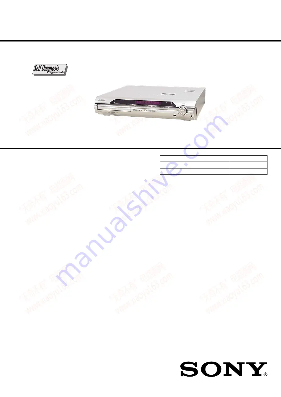
SERVICE MANUAL

Sony Corporation

Audio Business Group
Published by Sony Techno Create Corporation

US Model

Canadian Model

DVD RECEIVER

9-887-186-03

2007J16-1
© 2007.10

Ver. 1.2  2007.10

HCD-DX315

HCD-DX315 is the amplifier, DVD/CD and tuner
section in DAV-DX315.

SPECIFICATIONS

Model Name Using Similar Mechanism

HCD-DX155

Mechanism Type

CDM81C-DVBU101

Optical Pick-up Name

KHM-310CAB

This system incorporates with Dolby*

1

 Digital and Dolby Pro Logic (II)

adaptive matrix surround decoder and the DTS*

2

  Digital Surround

System.
*1 Manufactured under license from Dolby Laboratories.

“Dolby,” “Pro Logic,” and the double-D symbol are trademarks of
Dolby Laboratories.

*2 Manufactured under license from Digital Theater Systems, Inc.

“DTS” and “DTS Digital Surround” are trademarks of Digital
Theater Systems, Inc.

— Continued on next page —

AUDIO POWER SPECIFICATIONS
for the US model

POWER OUTPUT AND 
TOTAL HARMONIC 
DISTORTION 
(FTC Output Power): 

FL/FR/LS/RS/C: 84 W/ch 
3 ohm at 170 - 20,000 Hz,
0.7 % THD 
SW: 160 W 1.5 ohm at 40 - 
170 Hz, 0.7 % THD

Amplifier section

US models:
Surround mode (reference) RMS output 
power, 10 % 

THD
Front: 143
 W + 143 W 
(with SS-TS53)

Center*: 143 W
(with SS-CT51)
Surround*
: 143 W + 143 
W
(with SS-TS5
1)
Subwoofer*: 285 W
(with SS-WS52B)

Other models:
Stereo mode (rated)

108 W + 108 W (3 ohms at 
1 kHz, 1 % THD)

Surround mode (reference) RMS output power, 10 % 

THD
Front: 143 W + 143 W 
(with SS-TS53)
Center*: 143 W
(with SS-CT51)
Surround*: 143 W + 143 
W
(with SS-TS51)
Subwoofer*: 285 W
(with SS-WS52B)

* Depending on the sound field settings and the source, 

there may be no sound output.

Inputs
TV/VCR (AUDIO IN)

Sensitivity: 450/250 mV

AUDIO IN/MIC

Sensitivity: 250/125 mV

Outputs (Analog)
Phones

Accepts low-and high-
impedance headphones.

DVD system

Laser


Semiconductor laser

(DVD: 

λ

 = 650 nm)

(CD: 

λ

 = 790 nm)

Emission duration: 
continuous

Signal format system

NTSC 

Tuner section

System

PLL quartz-locked digital 
synthesizer system

FM tuner section
Tuning range 

87.5 – 108.0 MHz 
(100 kHz step)

Antenna (aerial)

FM wire antenna (aerial)

Antenna (aerial) terminals 75 ohms, unbalanced
Intermediate frequency

10.7 MHz

AM tuner section
Tuning range 

530-1,710 kHz (with the 
interval set at 10 kHz)
531-1,710 kHz (with the 
interval set at 9 kHz)

Antenna (aerial)

AM loop antenna (aerial)

Intermediate frequency

450 kHz

www. xiaoyu163. com

QQ 376315150

9

9

2

8

9

4

2

9

8

TEL 13942296513

9

9

2

8

9

4

2

9

8

0

5

1

5

1

3

6

7

3

Q

Q

TEL  13942296513  QQ  376315150  892498299 

TEL  13942296513  QQ  376315150  892498299 

http://www.xiaoyu163.com

http://www.xiaoyu163.com

Summary of Contents for HCD-DX315

Page 1: ... 143 W with SS CT51 Surround 143 W 143 W with SS TS51 Subwoofer 285 W with SS WS52B Other models Stereo mode rated 108 W 108 W 3 ohms at 1 kHz 1 THD Surround mode reference RMS output power 10 THD Front 143 W 143 W with SS TS53 Center 143 W with SS CT51 Surround 143 W 143 W with SS TS51 Subwoofer 285 W with SS WS52B Depending on the sound field settings and the source there may be no sound output ...

Page 2: ... 1 A commercial leakage tester such as the Simpson 229 or RCA WT 540A Follow the manufacturers instructions to use these instruments 2 A battery operatedAC milliammeter The Data Precision 245 digital multimeter is suitable for this job 3 Measuring the voltage drop across a resistor by means of a VOM or battery operatedAC voltmeter The limit indication is 0 75 V so analog meters must have an accura...

Page 3: ...lder so use caution not to let solder bridges occur such as on IC pins etc Usable with ordinary solder It is best to use only unleaded solder but unleaded solder may also be added to ordinary solder Notes on chip component replacement Never reuse a disconnected chip component Notice that the minus side of a tantalum capacitor may be damaged by heat Flexible Circuit Board Repairing Keep the tempera...

Page 4: ...41 6 11 Schematic Diagram MAIN Board 4 10 42 6 12 Schematic Diagram MAIN Board 5 10 43 6 13 Schematic Diagram MAIN Board 6 10 44 6 14 Schematic Diagram MAIN Board 7 10 45 6 15 Schematic Diagram MAIN Board 8 10 46 6 16 Schematic Diagram MAIN Board 9 10 47 6 17 Schematic Diagram MAIN Board 10 10 48 6 18 Printed Wiring Board I O Board 49 6 19 Schematic Diagram I O Board 50 6 20 Printed Wiring Boards ...

Page 5: ...essage UNLOCKED is displayed and the tray is unlocked Note When LOCKED is displayed the tray lock is not released by turning power on off with the 1 button Note on MAIN board replacement New part of EEP ROM IC1103 on the MAIN board cannot be used Therefore if the mounted MAIN board A 1179 147 A is replaced exchange new EEP ROM IC1103 with that used before the replacement When the self diagnosis fu...

Page 6: ...MAIN board CN3002 30 V Parts face side Parts face side Connect the specified resistor between black and red leads gear tweezers 1 Insert tip of tweezers through the hole of bottom plate and roate the gear in the counter clockwise direction DVD lid tape 2 Attach an adhesive tape on the DVD LID and draw it out HOW TO OPEN THE DISC TABLE WHEN POWER SWITCH TURNS OFF www xiaoyu163 com QQ376315150 9 9 2...

Page 7: ...OP unit be sure to connect the flexible printed circuit board first of all before removing the static electricity prevention solder bridge by unsoldering Remove the static electricity prevention solder bridge by unsoldering after the flexible printed circuit board has already been connected Do not remove nor unsolder the solder bridge as long as the OP unit is kept standalone www xiaoyu163 com QQ3...

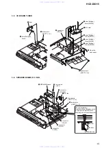
Page 8: ... MAIN board IC504 CN506 CN3002 CN3001 CN902 CN901 CN904 IC941 IC942 IC943 When re assembling leave 30 mm between harnesses A and B for safety harnesses A harnesses B clamp 30mm www xiaoyu163 com QQ376315150 9 9 2 8 9 4 2 9 8 TEL 13942296513 9 9 2 8 9 4 2 9 8 0 5 1 5 1 3 6 7 3 Q Q TEL 13942296513 QQ 376315150 892498299 TEL 13942296513 QQ 376315150 892498299 http www xiaoyu163 com http www xiaoyu163...

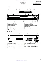
Page 9: ...ONITOR OUT S VIDEO VIDEO jacks 24 C AM terminal 13 D COAXIAL FM 75Ω jack 13 E TV VCR AUDIO IN R L jacks 27 F COMPONENT VIDEO OUT jacks 24 COAXIAL AM FM75 SPEAKER FRONT R FRONT L SUR R SUR L CENTER WOOFER COMPONENT VIDEO OUT TV VCR MONITOR OUT ANTENNA DVD ONLY Y PB CB PR CR R L AUDIO IN VIDEO DVD ONLY S VIDEO www xiaoyu163 com QQ376315150 9 9 2 8 9 4 2 9 8 TEL 13942296513 9 9 2 8 9 4 2 9 8 0 5 1 5 ...

Page 10: ...is selected Except for JPEG 32 G Playing status DVD function only H Lights up when the DYNAMIC BASS is selected 61 I Lights up when CD is loaded J Lights up when the system outputs progressive signals DVD function only 25 K Indicates the selected SPEAKER FORMATION 66 L Current surround format Except for JPEG M Displays system s status such as chapter title or track number time information radio fr...

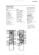
Page 11: ...OL eh 60 TV VIDEO 2 60 VOLUME 8 29 58 77 1 on standby 1 19 22 29 37 58 TV 1 on standby ej 60 C X x c qd 19 22 31 36 57 63 REPLAY ADVANCE 9 29 es wk 29 m M qs 0 35 SLOW qs 0 35 H play ea 29 37 64 STEP 9 35 x stop wl 30 37 63 X pause qa 30 DISPLAY wj 20 36 63 93 O RETURN ed 37 ef 60 The H number 5 and VOLUME buttons have tactile dots Use the tactile dots as references when operating the system ALPHA...

Page 12: ...VBU101 Page 20 3 13 OPTICAL PICK UP KHM 310CAB Page 20 3 5 I O BOARD TUNER Page 15 3 7 MAIN BOARD Page 16 3 8 POWER BOARD Page 17 3 6 SPEAKER BOARD D C FAN Page 15 3 2 CASE FRONT PANEL ASSY Page 13 SET 3 14 GEAR SUB TRAY 1 GEAR SUB TRAY 2 Page 21 3 15 LEVER ASSY Page 21 3 16 STOCKER SECTION Page 22 3 19 ROTARY ENCODER MD Page 23 3 17 CAM STOCKER Page 22 3 20 GEAR BU2 Page 24 3 18 GEAR STOCKER 3 Pa...

Page 13: ...e direction DVD lid tape 2 Attach an adhesive tape on the DVD LID and draw it out 8 sheet 9 wire flat type 23core CN509 qa connector CN312 qd claw qd claw qf front panel assy 5 two screws CASE3 TP2 When re assembling leave 30 mm between harnesses A and B for safety harnesses A harnesses B clamp 30mm www xiaoyu163 com QQ376315150 9 9 2 8 9 4 2 9 8 TEL 13942296513 9 9 2 8 9 4 2 9 8 0 5 1 5 1 3 6 7 3...

Page 14: ... FL board qf button power When reassembling route the harness and flexible cable as shown in the illustration 4 JACK board 5 eight screws BVTP 2 6 6 LED board 7 button disk indicator disk 9 button disk q button play 3 screw BVTP 2 6 1 knob vol 2 nut 8 five indicators disk www xiaoyu163 com QQ376315150 9 9 2 8 9 4 2 9 8 TEL 13942296513 9 9 2 8 9 4 2 9 8 0 5 1 5 1 3 6 7 3 Q Q TEL 13942296513 QQ 3763...

Page 15: ... two screws BVTP 4 8 8 two screws BVTT 3 8 1 connector CN3000 4 connector CN303 5 connector CN302 6 connector CN301 7 two screws BV3 9 SPEAKER board screw lead pin When assembling clamp the three harnesses with a lead pin or a similar tool so that they do not touch this screw three harnesses www xiaoyu163 com QQ376315150 9 9 2 8 9 4 2 9 8 TEL 13942296513 9 9 2 8 9 4 2 9 8 0 5 1 5 1 3 6 7 3 Q Q TEL...

Page 16: ... type 13core CN1301 8 connector CN302 9 connector CN301 q connector CN3000 qa connector CN3001 qs connector CN3002 qd connector CN515 qg two screws BVTP 3 8 wd clamp qj HEATSINK B board w heatsink AMP qh HEATSINK A board ql screw BVTP 3 12 qk two screws BV 3 When re assembling leave 30 mm between harnesses A and B for safety screw lead pin When assembling clamp the three harnesses with a lead pin ...

Page 17: ...ce install the connector POWER board MAIN board When re assembling leave 30 mm between harnesses A and B for safety harnesses A harnesses B clamp 30mm www xiaoyu163 com QQ376315150 9 9 2 8 9 4 2 9 8 TEL 13942296513 9 9 2 8 9 4 2 9 8 0 5 1 5 1 3 6 7 3 Q Q TEL 13942296513 QQ 376315150 892498299 TEL 13942296513 QQ 376315150 892498299 http www xiaoyu163 com http www xiaoyu163 com ...
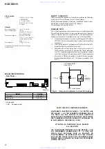
Page 18: ... cable harness 1 wire flat type 21core CN508 5 four screws BVTP 3 10 6DVD mechanism deck CDM81C DVBU101 www xiaoyu163 com QQ376315150 9 9 2 8 9 4 2 9 8 TEL 13942296513 9 9 2 8 9 4 2 9 8 0 5 1 5 1 3 6 7 3 Q Q TEL 13942296513 QQ 376315150 892498299 TEL 13942296513 QQ 376315150 892498299 http www xiaoyu163 com http www xiaoyu163 com ...

Page 19: ...he two points 6 M761 LD ST MOTOR 7 Remove soldering from the two points 8 M762 BU U D MOTOR 3 11 MOTOR BOARD M761 LD ST MOTOR M762 BU U D MOTOR www xiaoyu163 com QQ376315150 9 9 2 8 9 4 2 9 8 TEL 13942296513 9 9 2 8 9 4 2 9 8 0 5 1 5 1 3 6 7 3 Q Q TEL 13942296513 QQ 376315150 892498299 TEL 13942296513 QQ 376315150 892498299 http www xiaoyu163 com http www xiaoyu163 com ...
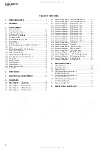
Page 20: ...ptical pick up KHM 310CAB 5 0 insulator qa insulator 8 insulator screw qs insulator 3 insulator screw 9 insulator 3 12 BASE UNIT DVBU101 3 13 OPTICAL PICK UP KHM 310CAB www xiaoyu163 com QQ376315150 9 9 2 8 9 4 2 9 8 TEL 13942296513 9 9 2 8 9 4 2 9 8 0 5 1 5 1 3 6 7 3 Q Q TEL 13942296513 QQ 376315150 892498299 TEL 13942296513 QQ 376315150 892498299 http www xiaoyu163 com http www xiaoyu163 com ...

Page 21: ... tray 4 lever sub tray shutter tray When re assembling insert the lever sub tray between the bosses of the shutter tray boss boss Before re assembling slide the cam BU in the direction of the arrow Before re assembling align the lever release and the lever sub tray with the lever mode as shown in the illustration dowel dowel 3 14 GEAR SUB TRAY 1 GEAR SUB TRAY 2 3 15 LEVER ASSY www xiaoyu163 com QQ...

Page 22: ...installing the cams stocker fix the gear stocker 3 in the manner so that the hole of the gear stocker 3 should be aligned with the hole of the chassis located beneath the gear stocker 3 Be sure to install the cams stocker in such a way that the grooves of the cams stocker face the direction of the arrows 3 16 STOCKER SECTION 3 17 CAM STOCKER www xiaoyu163 com QQ376315150 9 9 2 8 9 4 2 9 8 TEL 1394...

Page 23: ...ING ROTARY ENCODER MD INSTALLATION cam BU Slide the cam BU in the direction of the arrow so that the mark of the gear BU2 can be seen Engage the gears while aligning the mark of the gear BU2 with the protruding part of the rotary encoder protruding part mark 3 18 GEAR STOCKER 3 3 19 ROTARY ENCODER MD Ver 1 2 www xiaoyu163 com QQ376315150 9 9 2 8 9 4 2 9 8 TEL 13942296513 9 9 2 8 9 4 2 9 8 0 5 1 5 ...

Page 24: ...he cam BU in the direction of the arrow Assemble the gear BU2 in such a manner that the groove of the cam BU is aligned with the rib of the gear BU2 rib groove 3 20 GEAR BU2 Ver 1 2 www xiaoyu163 com QQ376315150 9 9 2 8 9 4 2 9 8 TEL 13942296513 9 9 2 8 9 4 2 9 8 0 5 1 5 1 3 6 7 3 Q Q TEL 13942296513 QQ 376315150 892498299 TEL 13942296513 QQ 376315150 892498299 http www xiaoyu163 com http www xiao...
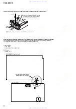
Page 25: ...This mode moves the optical pick up to the position durable to vibration and clears all data including preset data stored in the RAM to initial conditions Use this mode when returning the set to the customer after repair Procedure 1 Press the 1 button to turn the power on 2 Press the FUNCTION button to set the function DVD 3 Remove all discs and then press three buttons A and 1 simultaneously 4 Af...

Page 26: ... button on the remote commander The screen will appear as shown 3 Select 3 Manual Adjustment by pressing the 3 R button on the remote commander The screen will appear as shown 4 Select 6 IOP by pressing the 6 R button on the remote commander 5 Wait until a hexadecimal number appear 6 Convert each data from hexadecimal to decimal using conversion table 7 Please find the label on the rear of the BU ...

Page 27: ... Power OFF request when syscon hung up 19 Thermal shutdown 24 MoveSledHome error 25 Mechanical move error 5 Changer 26 Mechanical move stack error 30 DC motor adjustment error 31 DPD offset adjustment error 32 TE balance adjustment error 33 TE sensor adjustment error 34 TE loop gain adjustment error 35 FE loop gain adjustment error 36 Bad jitter after adjustment 40 Focus NG 42 Focus layer jump NG ...

Page 28: ...llowing procedure 1 From the Top Menu of Remocon Diagnosis Menu select 4 Version Information by pressing the 4 R button on the remote commander The following screen appears on the on screen display To return to the Top Menu of Remocon Diagnosis Menu press 0 R on the remote commander Ver 1 1 www xiaoyu163 com QQ376315150 9 9 2 8 9 4 2 9 8 TEL 13942296513 9 9 2 8 9 4 2 9 8 0 5 1 5 1 3 6 7 3 Q Q TEL ...

Page 29: ...sert the CD test disc refer to the TEST DISC LIST and press the H button to play the disc back 4 Confirm that oscilloscope waveform is clear and check RF signal level is correct or not Note A clear RF signal waveform means that the shape can be clearly distinguished at the center of the waveform 5 Eject the CD disc and insert the DVD SL test disc refer to the TEST DISC LIST and press the H button ...

Page 30: ... For Printed Wiring Boards Note X parts extracted from the component side a Through hole Pattern from the side which enables seeing The other layers patterns are not indicated Indication of transistor Caution Parts face side Parts on the parts face side seen from SIDE A the parts face are indicated Pattern face side Parts on the pattern face side seen from SIDE B the pattern face are indicated New...

Page 31: ... p 1 IC1101 6 DVDRFIP 200 mV DIV 100 ns DIV 900 mVp p 3 IC1101 z YUV3 500 mV DIV 20 µs DIV H 1 5 Vp p 7 IC201 wh COUT 8 IC201 wa YOUT qa IC201 qh CrOUT 9 IC201 w CYOUT 0 IC201 qk CbOUT 1 V DIV 20 µs DIV H 2 0 Vp p 1 V DIV 20 µs DIV 2 2 Vp p H 500 mV DIV 20 µs DIV H 1 6 Vp p 1 V DIV 20 µs DIV 2 2 Vp p H 1 6 Vp p H 500 mV DIV 20 µs DIV 6 IC201 wd CVBS 500 mV DIV 20 µs DIV H 2 5 Vp p w w w x i a o y ...

Page 32: ...OLLER 99 IFSCK DVD_SCO 33 100 XIFCS DVD_XIFCS 37 110 PRST MTK_RST SYSRST SCO SCD SID 98 IFSDO DVD_SOD 32 101 IFSDI CDM_OPEN_SW 105 IFBSY DVD_XIFBUSY 34 DVD_SID 31 TRO FMO FOO DMO TRO 10 13 16 17 FMO DMO 178 REV 174 FWD 211 MUTE123 210 MUTE 170 TSDM M M M M 28 V2REFO 106 RXD 107 TXD 5 6 2 1 RFMON CN1105 TO DIAG JIG V2REFO RXD TXD REG02 REG01 9 12 85 89 86 87 88 4 3 2 26 13 14 15 25 24 23 20 19 11 1...

Page 33: ...AMP LRCKO AMP D2 AMP D3 218 SDATA1 224 DWIDE 219 SDATA2 213 ALRCK 214 ABCK 215 ACLK IC501 2 4 SYSTEM CONTROL 82 A SEL0 83 A SEL1 69 TUNED TUNED 70 ST_CLK PLL CK PLL DO PLL CE PLL DI 71 ST_DO 72 ST_CE 73 ST_DI 91 ACAL MIC LEVEL 26 MIC GAIN 28 DC CONT 90 MONO ST DET 100 MIC A CALSW ACAL GAIN CONT MO ST DET PLUG DET1 80 V_SEL0 81 V_SEL1 V_SEL0 V_SEL1 J200 TV VCR TUNER UNIT L CH R CH L L R R TUNED PLL...

Page 34: ...0 LAT1 INIT NSPMUTE SOFTMUTE INIT SOFTMUTE SCDT SHIFT LAT1 LAT2 LAT3 SCDT SHIFT AMP_D1 MCK0 BCK0 LRCK0 LAT2 INIT NSPMUTE SCDT SHIFT AMP_D2 MCK0 BCK0 LRCK0 24 OVF FLAGR FLAGL OVF 25 19 SOFTMUTE 19 20 FL801 FLUORESCENT INDICATOR TUBE Q3551 PROTECT DETECT AMP_D1 D3 AMP_BCK0 LRCK0 MCK0 A AMP SECTION Page 33 1 DAMP SCDT 2 DAMP SHIFT SG1 SG16 HPMUTE PLUG_DET2 53 HP_MUTE MST 52 HP_SW 47 DAMP LAT1 48 DAMP...

Page 35: ...RA0 RA11 RA0 RA11 RD0 RD15 142 RCS 19 RCS 138 RWE 16 RWE 140 MRAS 18 RAS 139 CAS 17 CAS MDQM0 15 DQM0 MDQM1 39 DQM1 CLE 37 DRCLE 102 SCL 103 SDA 143 BA0 20 BS0 BA1 21 BS1 29 31 33 35 38 40 42 44 25 16 9 1 48 145 156 113 137 157 2 4 5 7 8 10 11 13 42 44 45 47 48 50 51 53 10 NC XROMCS XWR XRD 12 CBIN 4 CVBSIN 10 CYIN 2 CIN 6 YIN 25 S1 14 20 21 23 26 16 18 CRIN 2 1 S VIDEO DVD ONLY J201 J202 COMPONEN...

Page 36: ... POWER PROTECTION AC IN SW 3 3V 3 3V 5V PHOTO COUPLER PHOTO COUPLER REG IC1107 3 3V REG IC1105 3 3V REG IC942 D 5V REG IC943 3 3V REG IC951 VOLTAGE DETECT IC1109 1 8V REG IC3050 1 8V REG 6V SW 9V VOLTAGE DETECT Q901 VOLTAGE CONTROLLER Q945 MOTOR DRIVE CONTROLLER 3 3V IC516 5V REG A5V 9V A12V 1 8V D503 D505 E3 3V BMP3 3V 1 8V Q502 5V SW IC502 3 3V REG 3 3V SW 5V RECT OSC D3 3V RF F901 POWER Thermis...

Page 37: ...15 R3065 R1204 R1205 R1216 R1114 C1205 R1214 R1209 R1206 R1210 C1101 R1193 R1108 RB501 C1188 R1182 L3051 RB1104 R1161 R3401 R1118 R1148 R1141 R2553 R2551 R1181 R2546 R1191 R1107 R1121 C1167 R1152 C1152 C1195 C1151 C3073 C513 R2554 C507 R515 R728 R612 R616 R614 R1112 R1113 R1156 C1120 C1121 C1122 R2109 R1153 C1133 C1132 C1147 C1148 C1135 C1139 C1137 R1145 C1138 R1136 R1142 R1160 R1132 R2101 FL1107 ...

Page 38: ...R3125 R3124 R3122 CN3001 C3217 D3112 R3169 R3170 D3151 C3170 C3150 C3168 C3205 C3156 C3256 R3127 C3204 C3119 R3173 R3171 R3174 R3172 R597 R3177 R3175 C3253 R3176 C3221 R3553 R598 D3552 R3551 C3267 D3152 R3219 R3220 D3201 C3220 C3200 C3218 C3169 R3224 R3222 R3223 R3221 R3227 R3225 C3405 R3226 C3271 C3024 C3207 C3406 C3417 D3202 R3269 R3270 C3270 C3268 C3219 R3274 R3272 R3273 R3271 R3277 R3275 C3250...

Page 39: ... TP3001 TP3004 C2208 C2206 C2207 C2211 R2200 R2214 R2213 R2212 R2211 C2202 C2201 C2212 C2213 ICT503 ICT502 ICT501 ICT506 ICT505 ICT504 ICT512 ICT513 ICT510 ICT511 ICT507 ICT508 ICT509 0 0 0 0 0 0 0 0 0 0 0 0 10 50V 7L 10 50V 7L 10 50V 7L 47 16V 7L 47 16V CXD9788AR 47 16V CXD9788AR 2P 100 16V 2SD1616 TP LK 0 1 16V 0 1 16V 100 100 100 100k 1SS355WTE 17 1SS355WTE 17 1SS355WTE 17 1k 1k 1k 0 0 1 470 47...

Page 40: ...3415 R3403 R3407 TP3410 C3412 C3409 0 0022 50V B 0 0022 50V B 0 0022 50V B 0 0022 50V B 0 0022 50V B 0 0022 50V B 0 1 25V 2SC3052EF T1 LEF 100k 1 10W 100k 1 10W 100k 1 10W 10 10V F 100k 1 10W 100k 1 10W 100k 1 10W 2 2 16V F 100k 1 10W 1SS355WTE 17 1SS355WTE 17 10 50V 1 50V 0 0022 50V B 0 0022 50V B 0 0022 50V B 0 0022 50V B 0 0022 50V B 0 0022 50V B 0 0 1 50V 0 1 16V 0 1 16V 0 0 1 50V 0 1 16V 0 1 ...

Page 41: ... Q3081 CN3002 470 10V 470 10V NJM4565M TE2 100 10V SN74AHC1GU04DCKR 49 152 SMD 49TB 220 10V 0 22 47 16V CXD9788AR TK11118CSCL G 0 01 25V B 0 001 50V B 100 16V 0 100 220 16V 33k 1 10W 33k 1 10W 22k 1 10W 22k 1 10W 22k 1 10W 22k 1 10W 100p 50V CH 100p 50V CH 22k 1 10W 22k 1 10W 100p 50V CH 100p 50V CH 2 2k 1 10W 0 1 25V F 2 2k 1 10W 0 1 25V F 100p 50V CH 100p 50V CH 22k 1 10W 22k 1 10W 22k 1 10W 22k...

Page 42: ... 0 0022 50V B 0 0022 50V B 100k 1 10W 100k 1 10W 2 2 16V F 100k 1 10W 100k 1 10W 100k 1 10W 2 2 16V F 100k 1 10W 100k 1 10W 100k 1 10W 2 2 16V F 100k 1 10W 100k 1 10W 100k 1 10W 2 2 16V F 100k 1 10W 0 0022 50V B 0 0022 50V B 0 0022 50V B 0 0022 50V B 0 0022 50V B 0 0022 50V B 0 1 50V 0 1 16V 0 1 16V 0 0 1 50V 0 1 16V 0 1 16V 0 0 1 50V 0 1 16V 0 1 16V 4P SCN BOARD IN 4P SCN BOARD IN 0 033 50V 0 033...

Page 43: ...R597 R598 R513 R515 R742 CN507 ICT580 ICT581 C570 C716 C798 D504 C712 C799 C572 C571 C587 C589 IC511 C762 C856 IC501 C875 C855 EB1001 C503 C501 ICT514 ICT515 ICT516 ICT517 ICT518 ICT519 ICT520 ICT521 ICT525 ICT526 ICT527 ICT528 ICT529 ICT530 ICT531 ICT532 ICT533 ICT535 ICT534 ICT547 47k 10k M30622MEP A61FPU0 100 10k 2SC3052EF T1 LEF 0 22 16V B 47k 1k 10k 10k 100 100 100 100 100 100 100 100 100 100...

Page 44: ...FB504 FL503 FB506 FB503 FB507 EB903 FB508 RB501 C508 C509 C507 C506 FB509 C510 C512 C513 C511 CN509 ICT540 ICT539 ICT538 ICT536 ICT546 ICT543 ICT544 ICT545 ICT542 100 10V 100 1k 100 100 100 100 100 100 100 IC TA7805LS 47 16V 47 16V 12P JST PH 2MM 100 1k RSR025N03 47k 100 TK11133CSCL G 0 001 1SS355WTE 17 2200 6 3V 100 10V 0 1 0 33 47 16V 0 1 1SS355WTE 17 0UH 0UH 0UH 0UH 0UH 0UH 0UH EMI 0UH 0UH 0UH ...

Page 45: ... ICT1118 ICT1126 ICT1125 ICT1124 ICT1121 ICT1123 ICT1127 ICT1128 ICT1129 CL2501 Q1102 FL1101 Q1103 C1112 C1105 IC1107 C1117 C1118 C1119 C1124 Q1101 ICT569 10 50V 7L 10 50V 7L 10 50V 7L 24P 0 22 1 10W 0 5 22 1 10W 0 5 22 1 10W 0 5 22 22 22 47k 47k 0 10k 1M 100 47k 1k 0 01 25V B 0 01 25V B 0 01 25V B 100k 100k 100 0 22 16V B 0 22 16V B 0 01 25V B 1 10V B 1 10V B 1 10V B 1 10V B 0 1 16V B 0 1 16V B 0...

Page 46: ...141 R1142 R2547 R2548 R2549 R2550 R2551 R2554 RB1111 RB1103 RB1104 RB1115 RB1114 EB1003 ICT568 ICT570 ICT575 ICT576 ICT577 ICT578 ICT579 ICT567 IC1101 0 0 0 0 0 0 0 10k 150 150 150 150 150 1 10W 0 5 150 1 10W 0 5 0 10 50V 7L 47 1 10W 47 1 10W 47 47 0 2 2k XX 2W 10k 10k 10k 0 100 0 100 100k 0 01 25V B 0 01 25V B 0 01 25V B 0 01 25V B 15p 50V CH 10p 50V CH 0 1 16V B 0 001 25V CH 0 047 16V B 0 047 16...

Page 47: ...09 JL1711 JL1713 CN1105 Adjustment used IC1105 IC1104 RB1106 RB1105 FL1106 FL1104 FL1107 FL1108 C1190 C1187 C1178 C1177 C1179 R2176 R2546 FB1106 FB1111 RB1107 RB1108 FB1108 EB1004 ICT563 ICT564 ICT565 ICT566 ICT572 ICT573 EB1002 CN1301 47 16V 7L 47 16V 7L BR24L64F W E2 1k 1k 10k 10k 1 10V B 10k 1 10W 0 0 2 7k 3 3k 3 3k 3 3k 100 100 0 0 001 50V B 0 01 25V B 0 22 16V B 0 22 16V B 0 01 25V B 0 1 16V ...

Page 48: ... ICT549 ICT550 ICT551 ICT552 ICT553 ICT555 ICT554 ICT557 ICT556 IC1201 100k 1 10W 0 5 100k 1 10W 0 5 10k 33k 1 10W 0 5 10k 18k 1 10W 0 5 15k 1 10W 0 5 82k 1 10W 0 5 27k 10k 6 8k 47k 12k 1 10W 10k 1 2k 2 7k 33k 12k 15k 33k 0 01 25V B 0 033 16V B 0 033 16V B 0 01 25V B 0 001 50V B 0 01 25V B 0 01 25V B 0 01 25V B 0 1 16V B 0 1 16V B 0 01 25V B 220p 50V CH 220p 50V CH 0 01 25V B 47 16V 0 01 25V B 0 0...

Page 49: ...JW232 JW228 JW229 R235 R263 JW249 JW231 C351 C348 L202 R234 JW254 JW255 JW233 JW217 JW220 CN311 JW226 JW222 C352 JW273 C333 C334 JW267 JW253 R369 JW211 JW212 R368 R370 JW207 Q353 Q354 R367 JW223 JW269 L201 JW260 JW210 JW209 CN203 JW259 JW268 C234 C239 R376 R254 R253 R255 R256 C235 C236 Q360 JW227 JW257 JW275 R386 R381 R356 R344 R382 R343 R357 R375 C346 C345 R384 R358 C350 C349 R350 R349 Q361 Q362 ...

Page 50: ...28 C223 C225 C224 C226 C227 C228 C356 C355 C341 C342 C235 C242 IC201 L202 C201 C210 C213 C205 C354 J201 C345 C346 C349 C350 IC360 C351 J200 CN202 R234 R235 CN312 0 0 0 1 75 75 3P 10k 0 0 FFC 13P S 13P 150 0 5 150 0 5 150 0 5 150 0 5 150 0 5 150 0 5 9P 100k 100k 100k 100k 10 50V 10k 0 1 1000 6 3V 100 16V 100 16V 0 001 0 001 Y C 2P FFC 7P S AMP S 5P NJM4558M TE2 22 25V 22 25V 22 25V 100 16V 6 8k 6 8...

Page 51: ...800 C803 C801 Q801 R804 T801 JW806 R802 R811 D801 D805 D802 D804 CNP801 JW805 R814 R815 R816 C805 D803 C804 JW804 R801 JW801 JW803 C802 JW802 CN804 C851 S801 S807 D811 R832 S813 R831 R841 JW836 Q811 D812 Q812 R834 Q813 Q814 S812 JW814 Q815 R830 JW839 R835 JW837 JW838 JW840 JW841 Q816 D813 R836 S811 S808 R851 R852 R829 JW842 D814 S810 R838 Q817 JW844 Q819 JW843 R855 S804 R828 JW847 R856 S805 D815 R...

Page 52: ...KEY SW KEY 0 01 25V B 47 NJL23H400A 0UH 100 1 10W 100 1 10W 100 1 10W 10 16V 220p 50V B 220p 50V B 220p 50V B 220p 50V B 220p 50V B 220p 50V B 220p 50V B 220p 50V B 220p 50V B 220p 50V B 220p 50V B 3 9k 1 10W 1SS355WTE 17 33k 1 10W 100 CPH5504 TL E 0 2012 2SC3052EF T1 LEF 1k 100k 2 2k SW KEY 1k 1k 1k 1SS355WTE 17 1SS355W TE 17 1SS355W TE 17 23P FFC_1 0 L 1SS355WTE 17 1SS355W TE 17 220p 50V B 47 47...

Page 53: ...N301 CN302 42 40 42 EP301 EP302 CN302 CN301 C301 C302 C303 C304 C305 C306 C307 C308 C309 TB302 C310 C311 C312 TB301 C313 C314 C315 C316 C317 C318 C319 C320 C321 C322 C323 C324 CN303 EARTH PLATE EARTH PLATE VH S 2P EH S 4P 1000p 1000p 1000p 1000p 1000p 1000p 1000p 1000p 1000p DICS 2P NEW 1000p 1000p 1000p DICS 4P NEW 10000P 10000P 10000P 10000P 10000P 10000P 10000P 10000P 10000P 10000P 10000P 10000...

Page 54: ...N707 CN703 C762 C761 D701 D711 MOTOR BOARD SENSOR BOARD SW 2 BOARD SW 1 BOARD ENCODER BOARD RELAY BOARD 12 12 1 861 241 12 12 1 861 242 12 12 1 861 243 12 12 1 861 245 12 12 1 861 244 12 12 1 861 240 MAIN BOARD CN508 Page 38 D M761 LD ST MOTOR M762 BU U D MOTOR 4 3 2 1 G 1 1 1 1 1 1 1 1 6 2 3 3 3 3 1 1 2 2 3 4 1 2 3 4 G G 9 9 20 21 1 6 Semiconductor Location Ref No Location D701 D 4 D711 D 4 IC701...

Page 55: ...T 77 4 3A BA6956AN BU MTZJ T 77 4 7B 0 01 0 01 100 680 47 16V BA6956AN 3P 3P MAIN TRAY IN OUT 21PIN 10 16V 91 12k 2SC1740S QRT DISC SENSOR 10k 10k 10k 5P 5P ROTARY ENCODER MD ROTARY ENCODER 6P 6P ST E2 ST E3 ST E4 ST E1 ST E4 ST E3 ST E2 ST E1 5 10 CN508 Page 43 D See page 59 for IC Block Diagrams w w w x i a o y u 1 6 3 c o m Q Q 3 7 6 3 1 5 1 5 0 9 9 2 8 9 4 2 9 8 T E L 1 3 9 4 2 2 9 6 5 1 3 9 9...

Page 56: ...2 R956 R951 R955 R954 C952 R952 R953 C960 C953 D941 D944 C968 C967 JW941 JW940 D942 JW937 C946 C944 C958 JW942 C941 L945 L947 C942 C943 JW943 JW945 C951 D945 C971 JW936 R941 EB904 JW935 C954 L948 Q945 R958 C976 R957 C947 R946 R971 C945 C970 R966 CN904 R943 JW932 JW931 JW928 JW929 R948 C949 C955 C948 C969 R967 R968 EB903 JW930 C935 D931 C932 C933 L931 JW923 C939 C936 CN902 C934 JW925 R938 R937 R940...

Page 57: ... 50V HOLDER FUSE HOLDER FUSE 0 1 50V D5SBA60F01 2200 35V 2200 16V 100 10V 100 10V 0 1 50V 0 001 2kV 3300 10V 0 0047 50V 0 0047 50V 0 047 50V 470 1k 1 10W 3 3k 1 2W RT1N441C TP 1 0 1 25V 0 22 275V SARS03 0 01 250V 0 01 250V 0 22 275V 100p 250V STR V153 SI 3120KM TL SI 3050KM TL SI 3033KM TL VARISTOR TNR14SE471K490 22 100V 47p 2kV 470 10V 470 16V 470 25V 1000 16V 2P 0 1 0 1 0 1 0 1 0 1 0 1 1000 25V ...

Page 58: ... 45 46 47 48 Primary Clock System I O Board IC201 MM1623BFBE IC352 MC14052BDR2 1 VCC1 2 C IN 3 MUTE 1 4 CVBS IN 28 VCC2 23 CVBS OUT 25 S1 150kΩ BIAS 12 CB IN 150kΩ BIAS CLAMP 6dB 6dB 6 Y IN 7 GND1 8 BIAS CLAMP BIAS 6dB 9 I P 10 CY IN 11 CLP 13 MUTE2 5 YC MIX 6dB 6dB 6dB 27 S DC OUT 24 S2 LOW PASS FILTER 21 Y OUT 22 GND2 6 75MHz 75Ω DRIVER LOW PASS FILTER 6 75MHz 75Ω DRIVER 20 CY OUT 75Ω DRIVER S D...

Page 59: ...1 KEY2 VSS VDD SEG1 KS1 SEG2 KS2 SEG3 KS3 SEG4 KS4 SEG5 KS5 SEG6 KS6 SEG7 KS7 SEG8 KS8 SEG9 KS9 SEG10 KS10 SEG20 GRID9 SEG21 GRID8 SEG22 GRID7 SEG23 GRID6 SEG24 GRID5 GRID4 GRID3 GRID2 GRID1 VDD VSS SEG11 KS11 SEG12 KS12 SEG13 KS13 SEG14 KS14 SEG15 KS15 SEG16 KS16 VEE SEG17 GRID12 SEG18 GRID11 SEG19 GRID10 RELAY Board IC701 IC711 BA6956AN 1 2 3 4 5 6 7 8 9 CONTROL LOGIC TSD VREF OUT2 OUT1 RNF VM V...

Page 60: ...LED driver clock output 22 LED_LAT O LED driver latch 23 DIAT_CSOD I DIAT CSOD signal input Pull down 24 FL_D_OUT LED_DATA O FL and LED driver data output 25 FL_CS STB O FL driver chip select 26 MIC_GAIN O MIC gain control 27 CDM_OPEN_SW I CDM open switch input 28 DC_CONT O A CAL MIC DC control output 29 I2C_CLK I O I2C clock input Pull up 30 I2C_DATA I O I2C data input Pull up 31 DVD_SID O Media ...

Page 61: ...ound terminal 65 DIAT_XRST O DIAT reset not used 66 DIAT_XSCEN O DIAT chip enable not used 67 SRC_MODEO O Sampling rate convertor MODEO control not used 68 M_ST O LINK Multi STEREO control 69 TUNED I TUNER tuned input 70 ST_CLK O TUNER clock output 71 ST_DO I TUNER data input 72 ST_CE O TUNER chip enable output 73 ST_DI O TUNER data output 74 KEY INT I Wakeup from ECO mode by key input 75 RDS_CLK ...

Page 62: ...t input 93 MODEL I Model select input 94 KEY2 I Key input 2 input 95 KEY1 I Key input 1 input 96 VSS Ground terminal 97 KEY0 I Key input 0 input 98 VREF Reference voltage E3 3V 99 VCC Power supply BUP3 3V 100 MIC A CAL SW I MIC insert switch www xiaoyu163 com QQ376315150 9 9 2 8 9 4 2 9 8 TEL 13942296513 9 9 2 8 9 4 2 9 8 0 5 1 5 1 3 6 7 3 Q Q TEL 13942296513 QQ 376315150 892498299 TEL 13942296513...

Page 63: ...nput 21 MDI2 I Laser power PD monitor input 22 LDO2 O Laser drive output 23 LDO1 O Laser drive output 24 SVDD3 Power supply RF 3 3V 25 CSD O Central servo positive main beam summing output not used 26 RFLVL O RFRP low pass or Positive main beam summing output not used 27 SGND Ground terminal 28 V2REFO O Reference voltage 2 8V 29 V2O O Reference voltage 2 0V 30 VREFO O Reference voltage 1 4V 31 FED...

Page 64: ...put from PROM IC1102 89 IOA21 O Address bus 21 output to PROM IC1102 90 ALE O Address latch enable not used 91 AD7 I Data bus 7 input from PROM IC1102 92 A17 O Address bus 17 output to PROM IC1102 93 IOA0 O Address bus 0 output to PROM IC1102 94 DVSS Ground terminal 95 UWA I System controller write strobe not used 96 URD I System controller read strobe not used 97 DVDD18 Power supply 1 8V from IC1...

Page 65: ... DVSS Ground terminal 145 BA1 O BA1 signal output to SD RAM IC1104 146 RA10 O Address bus 10 output to SD RAM IC1104 147 RA0 O Address bus 0 output to SD RAM IC1104 148 DVSS Ground terminal 149 to 151 RA 1 to 3 O Address bus 1 to 3 output to SD RAM IC1104 152 DVDD18 Power supply 1 8V from IC1109 153 NC Reference voltage not used 154 NC Dram clock not used 155 DVDD3 Power supply SW 3 3V 156 RCLK O ...

Page 66: ...o VIDEO AMP IC201 201 DAVSS Ground terminal 202 YUV5 O Cb signal output to VIDEO AMP IC201 203 YUV6 O Cr signal output to VIDEO AMP IC201 204 DVDD3 Power supply SW 3 3V 205 MIC VSYNC I MIC_DET signal to IC501 not used 206 VOICE YUV7 Not used 207 KRMOD HSYNC O KARAOKE MODE signal to IC501 not used 208 SMSCK Not used 209 SPDATA SMSDI I Audio data of SPDIF input 210 MUTE O MUTE signal to IC1201 211 M...

Page 67: ... I Power supply RF 3 3V 240 NC I Not used 241 VSS Ground terminal 242 NC Not used 243 NC Not used 244 RFVDD3 Power supply RF 3 3V 245 RFRPDC I RFRP signal input 246 RFRPAC I RFRP signal input 247 HRFZC I High frequency RF ripple zero crossing 248 CRTPLP O Defect level filter capacitor connecting 249 RFGND Ground terminal 250 NC Not used 251 NC Not used 252 OSP O RF offset cancellation capacitor co...

Page 68: ...31 11 FAN D C 9 1 828 953 11 WIRE FLAT TYPE 9 CORE 1 7 685 646 79 SCREW BVTP 3X8 TYPE2 IT 3 3 7 685 881 09 SCREW BVTT 4X8 S 5 7 685 871 01 SCREW BVTT 3X6 S The components identified by mark 0 or dotted line with mark 0 are critical for safety Replace only with part number specified Les composants identifiés par une marque 0 sont critiques pour la sécurité Ne les remplacer que par une pièce portant...

Page 69: ... 64 A 1148 823 A LED BOARD COMPLETE 65 A 1148 824 A JACK BOARD COMPLETE 66 A 1148 821 A FL BOARD COMPLETE 67 1 828 384 11 WIRE FLAT TYPE 23 CORE 68 3 531 576 01 RIVET 7 2 FRONT PANEL SECTION 53 54 55 56 57 58 51 52 including S800 S800 Refer to page 78 60 67 60 66 60 60 68 60 61 62 63 64 65 59 not supplied not supplied not supplied not supplied Note If the wire flat type was replaced fold it some a...

Page 70: ...A 125V 1 7 685 646 79 SCREW BVTP 3X8 TYPE2 IT 3 2 7 685 648 79 SCREW BVTP 3X12 TYPE2 IT 3 4 7 685 647 79 SCREW BVTP 3X10 TYPE2 IT 3 7 3 CHASSIS SECTION New part of EEP ROM IC1103 on the MAIN board cannot be used Therefore if the mounted MAIN board A 1179 147 A is replaced exchange new EEP ROM IC1103 with that used before the replacement Note If the wire flat type was replaced fold it some as the w...

Page 71: ... 4 251 821 03 BRACKET TOP 164 4 251 922 01 PULLEY B 310 CHUCKING 165 4 251 824 01 LIFTER 166 4 251 837 01 PULLEY A 310 CHUCKING 167 4 218 253 52 SCREW M2 6 BTTP 6 7 685 534 19 SCREW BTP 2 6X8 TYPE2 N S 8 7 685 102 19 SCREW P 2X4 NON SLIT TYPE 2 Ref No Part No Description Remark Ref No Part No Description Remark 151 152 155 153 154 157 158 159 160 162 166 163 164 165 161 156 6 6 8 8 8 167 167 www x...

Page 72: ...AY 1 213 4 251 854 01 GEAR BU1 214 4 251 842 01 GEAR SUB TRAY 2 215 4 251 851 01 GEAR MAIN TRAY 2 216 4 218 253 52 SCREW M2 6 BTTP M761 A 4713 174 A MOTOR 81 ASSY LD ST MOTOR M762 A 4713 174 A MOTOR 81 ASSY BU U D MOTOR S771 1 478 552 11 ENCODER ROTARY MD 7 7 685 902 21 SCREW PTPWH 2 6X8 TYPE2 not supplied not supplied not supplied not supplied 201 202 203 203 204 209 214 215 203 214 210 206 207 2...

Page 73: ...CKER 270 4 251 861 01 LEVER SW 271 4 251 839 01 GEAR STOCKER 4 272 4 251 840 01 GEAR SUB TRAY 273 4 251 847 01 GEAR SS4 274 4 218 253 52 SCREW M2 6 BTTP S781 1 478 551 11 ENCODER ROTARY ST U D ENCORDER 7 7 685 902 21 SCREW PTPWH 2 6X8 TYPE2 Ref No Part No Description Remark Ref No Part No Description Remark 7 6 DVD MECHANISM DECK SECTION 3 CDM81C DVBU101 not supplied not supplied not supplied 251 ...

Page 74: ...SY 0302 8 820 291 02 OPTICAL PICK UP KHM 310CAB C2RP 303 2 634 618 01 INSULATOR 304 3 087 599 01 INSULATOR SCREW 6 7 685 534 19 SCREW BTP 2 6X8 TYPE2 N S www xiaoyu163 com QQ376315150 9 9 2 8 9 4 2 9 8 TEL 13942296513 9 9 2 8 9 4 2 9 8 0 5 1 5 1 3 6 7 3 Q Q TEL 13942296513 QQ 376315150 892498299 TEL 13942296513 QQ 376315150 892498299 http www xiaoyu163 com http www xiaoyu163 com ...
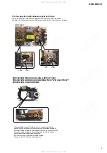
Page 75: ...PF 10 50V CONNECTOR CN801 1 779 560 21 CONNECTOR FFC LIF NON ZIF 23P CN805 1 785 336 11 PIN CONNECTOR LIGHT ANGLE 10P CN811 1 785 336 11 PIN CONNECTOR LIGHT ANGLE 10P CONNECTOR CNP801 1 785 328 11 PIN CONNECTOR LIGHT ANGRE 2P DIODE D431 6 501 193 01 DIODE 1SS355WTE 17 D432 6 501 193 01 DIODE 1SS355WTE 17 D801 6 501 193 01 DIODE 1SS355WTE 17 D802 6 501 193 01 DIODE 1SS355WTE 17 D803 8 719 069 56 DI...

Page 76: ...1 CONNECTOR FFC LIF NON ZIF 13P CN312 1 785 317 11 PIN CONNECTOR STRAIGHT 5P IC IC201 6 705 602 01 IC MM1623BFBE IC352 8 759 385 76 IC MC14052 BDR2 IC353 8 759 100 96 IC NJM4558M TE2 IC360 6 703 550 01 IC TA7809LS JACK J200 1 778 940 11 JACK 2P TV VCR J201 1 694 920 11 TERMINAL BOARD S TERMINAL 1P MONITOR OUT J202 1 817 601 11 JACK PIN 3P Y CB PB CR PR COMPONENT VIDEO OUT COIL L201 1 469 525 91 IN...

Page 77: ...DE 1SS355WTE 17 D470 6 501 193 01 DIODE 1SS355WTE 17 D492 6 501 193 01 DIODE 1SS355WTE 17 D493 6 501 193 01 DIODE 1SS355WTE 17 D496 6 501 193 01 DIODE 1SS355WTE 17 D497 6 501 193 01 DIODE 1SS355WTE 17 FERRITE BEAD FB410 1 469 144 21 FERRITE EMI SMD 2012 FB420 1 469 144 21 FERRITE EMI SMD 2012 FB450 1 216 864 11 SHORT CHIP 0 FB451 1 469 144 21 FERRITE EMI SMD 2012 FB460 1 216 864 11 SHORT CHIP 0 FB...

Page 78: ...R RT1P141C TP 1 Q815 8 729 027 23 TRANSISTOR RT1P141C TP 1 Q816 8 729 027 23 TRANSISTOR RT1P141C TP 1 Q817 8 729 027 23 TRANSISTOR RT1P141C TP 1 Q818 8 729 027 23 TRANSISTOR RT1P141C TP 1 Q819 8 729 027 23 TRANSISTOR RT1P141C TP 1 Q820 8 729 027 23 TRANSISTOR RT1P141C TP 1 RESISTOR R806 1 216 809 11 METAL CHIP 100 5 1 10W R807 1 216 809 11 METAL CHIP 100 5 1 10W R808 1 216 809 11 METAL CHIP 100 5 ...

Page 79: ...C1131 1 125 838 11 CERAMIC CHIP 2 2uF 10 6 3V C1132 1 107 826 11 CERAMIC CHIP 0 1uF 10 16V C1133 1 107 826 11 CERAMIC CHIP 0 1uF 10 16V C1135 1 164 677 11 CERAMIC CHIP 0 033uF 10 16V C1136 1 162 970 11 CERAMIC CHIP 0 01uF 10 25V C1137 1 107 826 11 CERAMIC CHIP 0 1uF 10 16V C1138 1 162 964 11 CERAMIC CHIP 0 001uF 10 50V C1139 1 162 919 11 CERAMIC CHIP 22PF 5 50V C1140 1 107 826 11 CERAMIC CHIP 0 1u...

Page 80: ... 1uF 25V C3038 1 164 156 11 CERAMIC CHIP 0 1uF 25V C3039 1 164 156 11 CERAMIC CHIP 0 1uF 25V C3040 1 164 156 11 CERAMIC CHIP 0 1uF 25V C3051 1 115 339 11 CERAMIC CHIP 0 1uF 10 50V C3052 1 165 908 11 CERAMIC CHIP 1uF 10 10V C3053 1 162 964 11 CERAMIC CHIP 0 001uF 10 50V C3054 1 126 933 11 ELECT 100uF 20 16V C3055 1 162 970 11 CERAMIC CHIP 0 01uF 10 25V C3056 1 126 923 91 ELECT 220uF 20 10V C3057 1 ...

Page 81: ...V C3273 1 162 964 11 CERAMIC CHIP 0 001uF 10 50V C3300 1 104 329 11 CERAMIC CHIP 0 1uF 10 50V C3303 1 107 725 11 CERAMIC CHIP 0 1uF 10 16V C3304 1 164 156 11 CERAMIC CHIP 0 1uF 25V C3305 1 107 725 11 CERAMIC CHIP 0 1uF 10 16V C3306 1 115 185 11 CERAMIC CHIP 0 033uF 10 50V C3307 1 115 185 11 CERAMIC CHIP 0 033uF 10 50V C3308 1 104 329 11 CERAMIC CHIP 0 1uF 10 50V C3309 1 112 246 11 ELECT 100uF 20 3...

Page 82: ...B3003 1 537 770 21 TERMINAL BOARD GROUND EB3004 1 537 770 21 TERMINAL BOARD GROUND EB3005 1 537 770 21 TERMINAL BOARD GROUND FERRITE BEAD FB500 1 469 324 21 FERRITE EMI SMD 2012 FB501 1 469 324 21 FERRITE EMI SMD 2012 FB502 1 469 324 21 FERRITE EMI SMD 2012 FB503 1 469 324 21 FERRITE EMI SMD 2012 FB504 1 469 324 21 FERRITE EMI SMD 2012 FB505 1 469 324 21 FERRITE EMI SMD 2012 FB506 1 469 324 21 FER...

Page 83: ...10W R589 1 216 809 11 METAL CHIP 100 5 1 10W R590 1 216 809 11 METAL CHIP 100 5 1 10W R591 1 216 809 11 METAL CHIP 100 5 1 10W R592 1 216 833 11 METAL CHIP 10K 5 1 10W R593 1 216 833 11 METAL CHIP 10K 5 1 10W R594 1 216 809 11 METAL CHIP 100 5 1 10W R595 1 216 809 11 METAL CHIP 100 5 1 10W R596 1 216 841 11 METAL CHIP 47K 5 1 10W R597 1 216 809 11 METAL CHIP 100 5 1 10W R598 1 216 809 11 METAL CHI...

Page 84: ...16 805 11 METAL CHIP 47 5 1 10W R1182 1 216 805 11 METAL CHIP 47 5 1 10W R1191 1 216 821 11 METAL CHIP 1K 5 1 10W R1193 1 216 821 11 METAL CHIP 1K 5 1 10W R1204 1 216 822 11 METAL CHIP 1 2K 5 1 10W R1205 1 216 833 11 METAL CHIP 10K 5 1 10W R1206 1 216 833 11 METAL CHIP 10K 5 1 10W R1207 1 216 826 11 METAL CHIP 2 7K 5 1 10W R1208 1 216 839 11 METAL CHIP 33K 5 1 10W R1209 1 216 839 11 METAL CHIP 33K...

Page 85: ...821 11 METAL CHIP 1K 5 1 10W R3064 1 216 821 11 METAL CHIP 1K 5 1 10W R3065 1 216 821 11 METAL CHIP 1K 5 1 10W R3066 1 216 809 11 METAL CHIP 100 5 1 10W R3067 1 216 809 11 METAL CHIP 100 5 1 10W R3068 1 216 809 11 METAL CHIP 100 5 1 10W R3069 1 216 809 11 METAL CHIP 100 5 1 10W R3070 1 216 809 11 METAL CHIP 100 5 1 10W R3071 1 216 809 11 METAL CHIP 100 5 1 10W R3072 1 216 809 11 METAL CHIP 100 5 1...

Page 86: ...16 809 11 METAL CHIP 100 5 1 10W R3402 1 216 809 11 METAL CHIP 100 5 1 10W R3403 1 216 797 11 METAL CHIP 10 5 1 10W R3404 1 216 864 11 SHORT CHIP 0 R3407 1 216 835 11 METAL CHIP 15K 5 1 10W R3415 1 216 797 11 METAL CHIP 10 5 1 10W R3416 1 216 797 11 METAL CHIP 10 5 1 10W R3419 1 216 136 00 RES CHIP 2 7 5 1 8W R3420 1 216 136 00 RES CHIP 2 7 5 1 8W R3421 1 216 833 11 METAL CHIP 10K 5 1 10W R3422 1 ...

Page 87: ...1uF 10 25V C960 1 100 566 91 CERAMIC CHIP 0 1uF 10 25V 0C963 1 113 907 51 CERAMIC 0 0022uF 99 250V 0C964 1 113 907 51 CERAMIC 0 0022uF 99 250V C967 1 100 566 91 CERAMIC CHIP 0 1uF 10 25V C968 1 100 566 91 CERAMIC CHIP 0 1uF 10 25V C969 1 100 566 91 CERAMIC CHIP 0 1uF 10 25V C970 1 100 566 91 CERAMIC CHIP 0 1uF 10 25V C971 1 100 566 91 CERAMIC CHIP 0 1uF 10 25V C976 1 126 933 11 ELECT 100uF 20 16V ...

Page 88: ...10W R936 1 216 853 11 METAL CHIP 470K 5 1 10W R937 1 216 833 11 METAL CHIP 10K 5 1 10W R938 1 216 821 11 METAL CHIP 1K 5 1 10W R939 1 218 859 11 METAL CHIP 3 3K 0 5 1 10W R940 1 216 833 11 METAL CHIP 10K 5 1 10W R941 1 216 864 11 SHORT CHIP 0 R943 1 216 864 11 SHORT CHIP 0 R946 1 216 811 11 METAL CHIP 150 5 1 10W R948 1 216 833 11 METAL CHIP 10K 5 1 10W R949 1 216 821 11 METAL CHIP 1K 5 1 10W R951...

Page 89: ...ERAMIC CHIP 0 01uF 10 50V C323 1 163 021 91 CERAMIC CHIP 0 01uF 10 50V C324 1 163 021 91 CERAMIC CHIP 0 01uF 10 50V CONNECTOR CN301 1 564 507 11 PLUG CONNECTOR 4P CN302 1 564 320 00 PIN CONNECTOR 3 96mm PITCH 2P CN303 1 564 509 11 PLUG CONNECTOR 6P GROUND TERMINAL BOARD EP301 1 537 770 21 TERMINAL BOARD GROUND EP302 1 537 770 21 TERMINAL BOARD GROUND TERMINAL TB301 1 780 344 11 TERMINAL BOARD SPEA...

Page 90: ...r Date Description of Revision 1 0 2006 04 New 1 1 2006 09 Correction of Test mode ENG 06006 1 2 2007 10 Correction of parts number for Ref No 211 and 213 SPM 07096 www xiaoyu163 com QQ376315150 9 9 2 8 9 4 2 9 8 TEL 13942296513 9 9 2 8 9 4 2 9 8 0 5 1 5 1 3 6 7 3 Q Q TEL 13942296513 QQ 376315150 892498299 TEL 13942296513 QQ 376315150 892498299 http www xiaoyu163 com http www xiaoyu163 com ...

Reviews: