14
HCD-DZ110/DZ111/DZ120/DZ120K
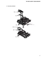
3-6. MAIN BOARD
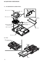
3-5. I/O BOARD (DZ120/DZ120K), I/O SCART BOARD (DZ110/DZ111)
7
I/O SCART
board
7
I/O board
qd
SPEAKER
board
qs
two screws
(+BV 3 x 6)
6
three screws
(+BVTP 3
×
8)
(DZ120/DZ120K model)
(DZ110/DZ111 model)
(DZ110/DZ111
model)
6
four screws
(+BVTP 3
×
8)
8
connector (CN303)
9
connector (CN302)
5
wire (flat type)
9core (CN101)(DZ120/DZ120K)
11core (CN101)(DZ110/DZ111)
1
connector
(CN302) (DZ110/DZ111)
(CN312) (DZ120/DZ120K)
4
wire (flat type)
13core (CN201)(DZ120/DZ120K)
13core (CN201)(DZ110/DZ111)
2
wire (flat type)
7core (CN202)(DZ120/DZ120K)
7core (CN304)(DZ110/DZ111)
3
wire (flat type)
13core (CN311)(DZ120/DZ120K)
21core (CN301)(DZ110/DZ111)
qa
two screws
(+BVTP 3
×
8)
q;
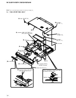
connector (CN301)
screw
lead pin
When assembling,
clamp the three harnesses with
a lead pin or a similar tool so
that they do not touch this screw.
three harnesses
9
connector
(CN3000)
6
wire (flat type)
23core (CN509)
5
wire (flat type) 5core (CN1202)
3
wire (flat type) 24core (CN1101)
2
wire (flat type) 7core (CN1302)
1
wire (flat type) 13core (CN1301)
q;
two screws (+BV 3 x 8)
qk
four screws (+BV 3 x 6)
w;
MAIN board
qj
four screws (+BV 3 x6)
7
connector (CN515)
4
connector (CN1201)
ql
two clamps
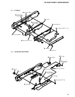
When re-assembling, attaching the
two heat radiation sheets on the
IC MAIN board first, and then attach
the heat sink (AMP).
heatsink (AMP)
radiation
sheets
IC on the
MAIN board
qs
HEATSINK B board
qg
heatsink (AMP)
qa
HEATSINK A board
qf
screw
(+BVTP 3
×
12)
qh
two radiation
sheet
8
connector
(CN3002)
When re-assembling, leave 30 mm between
harnesses A and B for safety.
harnesses A
harnesses B
30mm
qd
two screws
(+BVTP 3
×
10)

