33
HCD-DZ830W/DZ850KW
SECTION 5
ELECTRICAL ADJUSTMENT
DVD SECTION
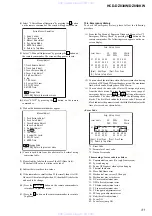
When the optical pick-up assy is replaced, perform the “Executing
IOP Measurement”.
Executing IOP Measurement (See page 30)
[FM Tune Level Check]
Procedure:
1. Turn the power on.
2. Input the following signal from Signal Generator to FM
antenna input directly.
* Carrier Freq : A = 87.5 MHz, B = 98 MHz, C = 108 MHz
Deviation
: 75 kHz
Modulation : 1 kHz
ANT input : 35 dBu (EMF)
Note:
Please use 75 ohm “coaxial cable” to connect SG and the set. You
cannot use video cable for checking.
Please use SG whose output impedance is 75 ohm.
3. Set to FM tuner function and tune A, B and C signals.
4. Confirm “TUNED” is lit on the display for A, B and C signals.
The mark of “TUNED” means “The selected station signal is
received in good condition.”
TUNER SECTION
generator
OUT (75
Ω
)
SET
DIAT SECTION
DIAT SIGNAL RF LEVEL ADJUSTMENT
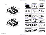
This adjustment is performed in order to adjust the transmission
distance of RF signal for DIAT communication.
Connection:
Procedure:
1. Connect the oscilloscope to TP1815 and GND on the DIAT-
TX board.
2. Connect DIR-T1 to DIR-T1 jack
(DIAT-TX board: J1801).
3. Confirm trigger is locked.
4. Adjust RV1801 on the DIAT-TX board so that the center of
waveform becomes 2.2 to 2.4 Vp-p.
RF Signal Reference Waveform
VOLT/DIV : 500 mV
TIME/DIV : 500 ns
level : 2.2 to 2.4 Vp-p
TP1815
DIAT-TX board
oscilloscope
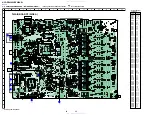
Adjustment Location:
– DIAT- TX Board (SIDE A) –
CN1801
RV1801
CN1802
J1801
TP1815
www. xiaoyu163. com
QQ 376315150
9
9
2
8
9
4
2
9
8
TEL 13942296513
9
9
2
8
9
4
2
9
8
0
5
1
5
1
3
6
7
3
Q
Q
TEL 13942296513 QQ 376315150 892498299
TEL 13942296513 QQ 376315150 892498299


