8
HCD-RV660D/RV990D
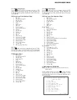
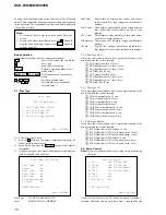
• Example display
### Syscon Diagnosis ###
Diag All Check
No.2 Version
2-3. ROM Check Sum
Check Sum = xxxx
Press NEXT Key to Continue
Press PREV Key to Repeat
For the ROM Check, the check sum calculated by the Syscon is
output, and therefore you must compare it with the specified value
for confirmation.
Following the message, press the NEXT
>
button to go to the
next item, or press the
.
PREV button to repeat the same
operation again.
To quit the diagnosis and return to Check Menu screen, press the
ENTER button on the remote commander to display Check Menu.
• Error occurred
If an error occurred, the diagnosis is suspended and error is displayed.
Press the ENTER button on the remote commander to quit the
diagnosis, or press the
.
PREV button to repeat the same check
where an error occurred, or press the NEXT
>
button to continue
the check from the item next to faulty item.
General Description of Checking Method
Selecting 2 and subsequent items calls the submenu screen of each
item. And selecting 2 and subsequent items executes respective
menus and outputs the results.
For the contents of each sub menu, see “Check Items List” as below.
Check Items List:
0-2. Version
0-2-1. All
0-2-2. Revision
0-2-3. ROM Check Sum
0-2-4. Model Type
0-2-5. Region
0-3. EEPROM Check
0-3-1. Sampling Check
0-3-2. Detail Check
0-4. GP I/O Check
0-5. SD Bus Check
0-6. Video Check
0-2. Version
0-2-2. Revision
The revision number of ROM (IC206) that the program for
the DVD system processor (IC207) is stored.
0-2-3. ROM Check Sum
Check sum is calculated.
(4 digits hexadecimal number)
0-2-4. Model Type
Model name is displayed. (MHC-RVXXXD)
0-2-5. Region
Model destination code is displayed. (2 digits number)
0-3. EEPROM Check
0-3-1. Sampling Check
EEPROM check at every 64 words.
It compares read data with write data of each address. When
there are discrepancies between two data, it displays error.
0-3-2. Detail Check
EEPROM check at every 1 word.
It compares read data with write data of each address. When
there are discrepancies between two data, it displays error.
0-4. GP I/O Check
Pull up/down setting check of the DVD system processor (IC207)
pin 150, 151 and 154 (for clock setting port).
0-5. SD Bus Check
SD bus data check between DVD decoder (IC701) and D-RAM
(IC706).
0-6. Video Check
Output the color bars for video level adjustment.
1. DRIVE AUTO ADJUSTMENT
On the Test Mode Menu screen, press the 1 button on the remote
commander, and the Adjustment Menu will be displayed.
## Drive Auto Adjustment ##
Adjustment Menu
0. ALL
1. DVD-SL
2. CD
3. DVD-DL
Exit: RETURN
Normally, 10/0 button is selected to adjust DVD (single layer), CD
and DVD (dual layers) in this order. But, individual items can be
adjusted for the case where adjustment is suspended due to an error.
In this mode, the adjustment can be made easily through the
operation following the message displayed on the monitor screen.
The disc used for adjustment must be the one specified for
adjustment.
1-0. ALL
Press the 10/0 button on the remote commander, and the servo set
data in EEPROM will be initialized. Then, 1. DVD-SL disc, 2. CD
disc and 3. DVD-DL disc are adjusted in this order.
Each time one disc was adjusted, it is ejected. Replace it with the
specified disc following the message. You can finish the adjustment
by pressing the RETURN button on the remote commander.
Note:
During adjustment of each disc, the measurement for disc
type judgment is made. As automatic adjustment does not
judge the disc type unlike conventional models, take care
not to insert wrong type discs. Also, do not give a shock
during adjustment.


