– 10 –
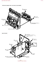
COVER
Note:
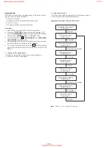
Follow the disassembly procedure in the numerical order given.
SECTION 3
DISASSEMBLY
3
two screws
(case 3TP2) (3
×
8)
2
screw
(case 3TP2) (3
×
12)
1
three screws
(BVTP3
×
8)
6
cover
2
screw
(case 3TP2) (3
×
12)
3
two screws
(case 3TP2) (3
×
8)
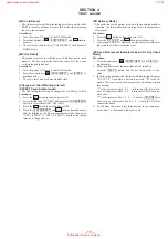
5
4
4
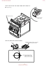
LOADING PANEL ASS’Y
3
loading panel ass’y
2
Pull-out
the disc tray.
1
Turn the cam-in the
direction of the arrow
A
.
A
www.freeservicemanuals.info
1/11/16
Published in Heiloo, Holland.

