69
HCD-WZ8D
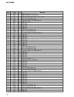
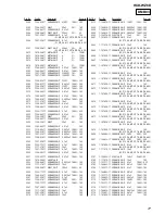
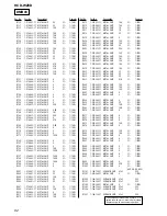
Pin No.
57
58
59
60
61
62
63
64
65
66
67
68
69
70
71
72
73
74
75
76
77
78
79
80
81
82
83
84
85
86
87
88
89 to 96
97
98
99
100
Pin Name
CONTROL 2
GFS DVD
MUTE CD
MUTE 2D
SLED
FG
SP ON
JIT
TE
PI
FE
AVSS
AVREF
AVDD
GFS CD
SCLK CD
TSD
FOK CD
LOCK CD
LDSEL
SACD/DVD
I2C SIO
I2C SCL
RXD
TXD
SDCLK RF
SDATA RF
XWR
XRD
(PWE)
VDD
VSS
A0 to A7
DSAVE
XDRST
WP EEP
SCL EEP
I/O
I
I
O
O
I
I
O
I
I
I
I
—
I
—
I
O
O
I
I
O
O
I/O
I/O
I
O
O
I/O
O
O
—
—
—
O
O
O
O
O
Description
Disc tray out detection signal input terminal Not used
Guard frame sync signal input from the DVD decoder
Muting on/off control signal output to the digital signal processor “H”: muting on
Muting on/off control signal output to the motor/coil driver “H”: muting on
Sled motor servo drive PWM signal input terminal
Spindle motor control signal input
Muting on/off control signal output to the motor/coil driver “H”: muting on
Jitter signal input
Tracking error signal input from the DVD/CD RF amplifier
Pull in signal input from the DVD/CD RF amplifier
Focus error signal input from the DVD/CD RF amplifier
Ground terminal (for A/D converter)
Reference voltage input terminal (for A/D converter)
Power supply terminal (+3.3V) (for A/D converter)
Guard frame sync signal input from the digital signal processor
SENSE serial data reading clock signal output to the digital signal processor
Thermal shut down signal output to the motor/coil driver
Focus OK signal input from the digital signal processor
GFS is sampled by 460 Hz “H” input when GFS is “H”
Laser diode selection signal output
“SACD/DVD selection signal output “L”: DVD, “H”: SACD”
Communication data bus with the DVD system processor and system controller
Communication data reading clock signal input or transfer clock signal output with the DVD system processor
and system controller
Serial data input from the RS-232C (for check)
Serial data output to the RS-232C (for check)
Serial data transfer clock signal output to the DVD/CD RF amplifier
Two-way data bus with the DVD/CD RF amplifier
Write strobe signal output to the DVD decoder
Read strobe signal output to the DVD decoder
Not used
Power supply terminal (+3.3V) (digital system)
Ground terminal (digital system)
Address signal output to the DVD decoder
Motor/coil driver power save control signal output terminal
Reset signal output to the digital signal processor and DSD decoder “L”: reset
Write protect signal output to the EEPROM
Clock signal output to the EEPROM


