background image

HCD-IS10

11

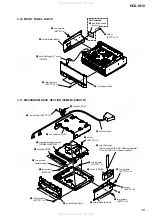
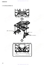
3-3. OPTICAL  PICK-UP  BLOCK (KHM-313CAB)

Note:

 Follow the disassembly procedure in the numerical order given.

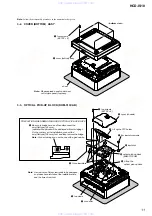
3-2. COVER (BOTTOM)  ASSY

1

four screws
(BVTP3 

×

 8)

2

cover (bottom) assy

sheet

Note:  Please spread a seat under a set 

not to injure panel (top) assy.

– bottom view –

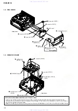
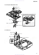
1

two screws
(BVTP3 

×

 8)

2

cover (chassis)

5

four insulator screws

9

insulator

9

three insulators

3

two claws

6

Lift up the
optical pick-up block.

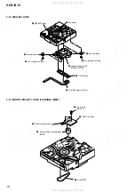
8

Be sure to bridge here, and then disconnect the
wire (flat type) (24 core).
(optical pick-up block will be destroyed without bridging.)
On the contrary at the installation, connect the
wire (flat type) (24 core) first, and then remove the bridge.
Note: For a soldering iron, use the one with a ground wire.

PRECAUTION WHEN REMOVING GOOD OPTICAL PICK-UP BLOCK

4

Lift up the FFC holder.

7

connector

0

optical pick-up block
(KHM-313CAB)

Note:  A screw hole of this screw tends to be damaged, 

so please be careful about the installation time 
and the time of removal.

www. xiaoyu163. com

QQ 376315150

9

9

2

8

9

4

2

9

8

TEL 13942296513

9

9

2

8

9

4

2

9

8

0

5

1

5

1

3

6

7

3

Q

Q

TEL  13942296513  QQ  376315150  892498299 

TEL  13942296513  QQ  376315150  892498299 

http://www.xiaoyu163.com

http://www.xiaoyu163.com

Summary of Contents for HD-IS10

Page 1: ...ntermediate frequency 450 kHz DVD RECEIVER US Model Canadian Model AEP Model UK Model E Model Australian Model Chinese Model HCD IS10 SPECIFICATIONS 9 887 730 02 2007J05 1 2007 10 Sony Corporation Home Audio Division Published by Sony Techno Create Corporation HCD IS10 is the DVD system tuner and video section in DAV IS10 In this set repair in the sate of having connected with SA WSIS10 Model Name...

Page 2: ... or performance of procedures other than those specified herein may result in hazardous radiation exposure When the self diagnosis function is activated to prevent the system from malfunctioning a 5 character service number e g C 13 50 with a combination of a letter and 4 digits appears on the TV screen or the front panel display In this case check the following table When letters numbers appear i...

Page 3: ... DVD Section 4 5 36 6 8 Schematic Diagram DVD Section 5 5 37 6 9 Printed Wiring Boards DVD Section 1 2 38 6 10 Printed Wiring Board DVD Section 2 2 39 6 11 Printed Wiring Board MAIN Board Component Side 40 6 12 Printed Wiring Board MAIN Board Conductor Side 41 6 13 Schematic Diagram MAIN Board 1 2 42 6 14 Schematic Diagram MAIN Board 2 2 43 6 15 Printed Wiring Board IO Board 44 6 16 Schematic Diag...

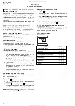
Page 4: ...ccur such as on IC pins etc Usable with ordinary solder It is best to use only unleaded solder but unleaded solder may also be added to ordinary solder RELEASING THE DISC SLOT LOCK The disc slot lock function for the antitheft of an demonstration disc in the store is equipped Releasing Procedure 1 Press the I 1 button to turn on the system 2 Press the FUNCTION button on the remote commander to sel...

Page 5: ...two sided disc product which mates DVD recorded material on one side with digital audio material on the other side However since the audio material side does not conform to the Compact Disc CD standard playback on this product is not guaranteed About Multi Session CD This system can play Multi Session CDs when an MP3 audio track is contained in the first session Any subsequent MP3 audio tracks rec...

Page 6: ...501 086 A to the MAIN board CN105 and wire flat type 19core wire flat type 19 core wire flat type 13 core Connect jig extension cable J 2501 244 A to the MAIN board CN103 and wire flat type 21core wire flat type 21 core Connect jig extension cable J 2501 102 A to the MAIN board CN106 and wire flat type 13 core MAIN board www xiaoyu163 com QQ376315150 9 9 2 8 9 4 2 9 8 TEL 13942296513 9 9 2 8 9 4 2...

Page 7: ...CE POSITION In checking the DVD mechanism deck prepare two extension jigs J 2501 086 A 19 cores 300 mm J 2501 102 A 13 cores 300 mm NOTE WHEN REMOVING OPTICAL PICK UP BLOCK Be sure to bridge here and then disconnect the wire flat type 24 core optical pick up block will be destroyed without bridging On the contrary at the installation connect the wire flat type 24 core first and then remove the bri...

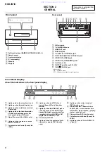
Page 8: ...cted G Current surround format Except for JPEG H Lights up when an NTSC disc is loaded Except US and Canadian models I Lights up when the HDMI OUT jack is correctly connected to HDCP high bandwidth digital content protection compliant device with HDMI or DVI digital visual interface input J Current repeat mode K Lights up when the system outputs progressive signals DVD function only L Lights up wh...

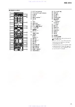
Page 9: ... TV CH 2 eg SUBTITLE eh ANGLE ej NIGHT ek DIMMER el SYSTEM MENU 1 The ENTER wj button is the same function as the ENTER 0 button 2 The 5 H TV CH and AUDIO buttons have tactile dots Use the tactile dots as references when operating the system 3 These buttons change to the TV operation buttons when the remote is in TV mode The remote is in TV mode when the TV mode indicator 2 lights up by pressing t...

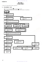
Page 10: ...6A DVBU101 Page 15 3 10 FRONT PANEL BLOCK Page 15 3 4 PANEL SIDE L R ASSY Page 12 3 5 PANEL TOP BLOCK SHIELD PLATE TOP Page 12 3 12 MD 86A ASSY Page 16 3 13 MOTOR PULLEY ASSY LOADING M001 Page 16 3 14 HOLDER BU ASSY Page 17 3 15 LEVER BU LOCK Page 17 3 16 CLOSE LEVER Page 18 3 17 LEVER DIR GEAR IDL B Page 18 3 18 CHASSIS TOP Page 19 3 19 LEVER LOADING L R Page 20 3 20 LEVER DISC SENSOR DISC STOP P...

Page 11: ...pick up block will be destroyed without bridging On the contrary at the installation connect the wire flat type 24 core first and then remove the bridge Note For a soldering iron use the one with a ground wire PRECAUTION WHEN REMOVING GOOD OPTICAL PICK UP BLOCK 4 Lift up the FFC holder 7 connector 0 optical pick up block KHM 313CAB Note A screw hole of this screw tends to be damaged so please be c...

Page 12: ... 8 2 screws BVTP3 8 5 three screws BVTP3 8 6 three screws BVTP3 8 4 two screws BVTP3 8 4 two screws BVTP3 8 7 shield plate top 1 wire flat type 11 core CN108 3 panel top block back view www xiaoyu163 com QQ376315150 9 9 2 8 9 4 2 9 8 TEL 13942296513 9 9 2 8 9 4 2 9 8 0 5 1 5 1 3 6 7 3 Q Q TEL 13942296513 QQ 376315150 892498299 TEL 13942296513 QQ 376315150 892498299 http www xiaoyu163 com http www ...

Page 13: ...7 wire flat type 19 core CN105 0 wire flat type 9 core CN110 qs wire flat type 13 core CN106 qf MAIN board qa wire flat type 11 core CN109 back view 1 wire flat type 21 core CN103 3 two screws BVTP3 8 6 five screws BVTP3 8 4 screw BVTT3 8 5 2 screw BVTP3 8 7 back panel HCD 8 IO board back view www xiaoyu163 com QQ376315150 9 9 2 8 9 4 2 9 8 TEL 13942296513 9 9 2 8 9 4 2 9 8 0 5 1 5 1 3 6 7 3 Q Q T...

Page 14: ...4 core connected or make a bridge as mentioned above and then disconnect the wire flat type 24 core Optical pick up will be destroyed without bridging On the contrary at the installation connect the wire flat type 24 core first and then remove the bridge Note For a soldering iron use the one with a ground wire Refer to DISASSEMBLY 3 2 OPTICAL PICK UP BLOCK KHM 313CAB PRECAUTION WHEN REMOVING WIRE ...

Page 15: ...bracket SYS 4 two screws BVTT2 6 6 2 screw BVTP3 8 7 tuner FM AM qa two screws BVTP2 6 qs two ground plates panel qd bracket CDM 0 system cable qf three screws BVTP3 8 qg shield plate front qh two screws BVTP3 8 qj sub chassis HCD qk screw BVTP3 8 6 wire flat type 9 core except AEP UK Russian models 11 core AEP UK Russian models www xiaoyu163 com QQ376315150 9 9 2 8 9 4 2 9 8 TEL 13942296513 9 9 2...

Page 16: ...two insulator screws 1 two claws 2 FFC holder 7 MD 86A assy 3 Remove two solders 2 two screws B2 6 8 5 MS 214 board 4 motor pully assy loading M001 1 belt MOT www xiaoyu163 com QQ376315150 9 9 2 8 9 4 2 9 8 TEL 13942296513 9 9 2 8 9 4 2 9 8 0 5 1 5 1 3 6 7 3 Q Q TEL 13942296513 QQ 376315150 892498299 TEL 13942296513 QQ 376315150 892498299 http www xiaoyu163 com http www xiaoyu163 com ...
Page 17: ... 4 LHL support 3 two screws B2 6 3 15 LEVER BU LOCK 3 three hooks 4 lever BU lock 2 gear BU lock 1 gear cap www xiaoyu163 com QQ376315150 9 9 2 8 9 4 2 9 8 TEL 13942296513 9 9 2 8 9 4 2 9 8 0 5 1 5 1 3 6 7 3 Q Q TEL 13942296513 QQ 376315150 892498299 TEL 13942296513 QQ 376315150 892498299 http www xiaoyu163 com http www xiaoyu163 com ...
Page 18: ... Lever DIR 6 gear IDL A qa gear IDL B 1 tension coil spring DIR 9 stoper 7 Loosen the screw 8 Hold the release lever and change the direction 5 gear cap www xiaoyu163 com QQ376315150 9 9 2 8 9 4 2 9 8 TEL 13942296513 9 9 2 8 9 4 2 9 8 0 5 1 5 1 3 6 7 3 Q Q TEL 13942296513 QQ 376315150 892498299 TEL 13942296513 QQ 376315150 892498299 http www xiaoyu163 com http www xiaoyu163 com ...
Page 19: ...o screws B2 10 5 chassis top 2 lever CL UP2 www xiaoyu163 com QQ376315150 9 9 2 8 9 4 2 9 8 TEL 13942296513 9 9 2 8 9 4 2 9 8 0 5 1 5 1 3 6 7 3 Q Q TEL 13942296513 QQ 376315150 892498299 TEL 13942296513 QQ 376315150 892498299 http www xiaoyu163 com http www xiaoyu163 com ...
Page 20: ...OADING R L INSTALLATION lever loading R Align the horizontal position lever loading L Install the both levers so that they move symmetrically www xiaoyu163 com QQ376315150 9 9 2 8 9 4 2 9 8 TEL 13942296513 9 9 2 8 9 4 2 9 8 0 5 1 5 1 3 6 7 3 Q Q TEL 13942296513 QQ 376315150 892498299 TEL 13942296513 QQ 376315150 892498299 http www xiaoyu163 com http www xiaoyu163 com ...

Page 21: ...sc sensor PRECAUTION DURING DISC STOP LEVER INSTALLATION 2 gear IDL L 3 21 GEAR IDL C 4 three hooks 2 two claws 6 claw 1 gear IDL F 7 gear IDL C 3 gear IDL D 5 lever gear loading assy www xiaoyu163 com QQ376315150 9 9 2 8 9 4 2 9 8 TEL 13942296513 9 9 2 8 9 4 2 9 8 0 5 1 5 1 3 6 7 3 Q Q TEL 13942296513 QQ 376315150 892498299 TEL 13942296513 QQ 376315150 892498299 http www xiaoyu163 com http www xi...

Page 22: ...t simultaneously and hold down until LOCKED or UNLOCKED displayed on the fluorescent indicator tube around 5 seconds 1 6 Demo Disc Play Mode to prevent theft of the demonstration disc Setting Procedure It automatically enters the mode when the demonstration disc is inserted Releasing Procedure 1 Press the I 1 button to turn the power on 2 Press the FUNCTION button on the remote commander to select...

Page 23: ... button on the remote commander to select the DMPORT CHK and press the ENTER button on the remote commander 7 The message DMPORT OK appears on the fluorescent indicator tube and enter the digital media port test mode Confirmation of communication line When NO DETECT and UART TO are displayed on the fluorescent indicator tube confirm the connection of the DMPORT check jig and enter the mode again E...

Page 24: ... Select 3 Manual Adjustment by pressing the 3 button on the remote commander The following screen appears on the on screen display Manual Adjust 1 Track Balance Adjust 2 Track Gain Adjust 3 Focus Balance Adjust 4 Focus Gain Adjust 5 Eq Boost Adjust 6 Iop 7 TRV Level 8 S curve FE Level 9 RFL PI Level 0 MIRR Time V v Change Value RETURN Return to previous menu 3 Select 6 Iop by pressing 6 button on ...

Page 25: ...or occurred Example of Error code 01 01 05 04 04 00 92 46 00 00 00 00 00 00 00 23 45 To Clear the Laser Hour Press the DISPLAY button on the remote commander and then press the CLEAR button on the remote commander The data for both CD and DVD data are reset Emg History Check Laser Hours CD 0h 0min DVD 0h 0min 01 01 05 04 04 00 92 46 00 00 00 00 00 00 00 23 45 02 02 02 01 01 00 A9 4B 00 00 00 00 00...

Page 26: ...the on screen display Version information Firm Main Ver X XXXX Firm Sub XX XX RISC XXXXXX 8032 XXXXXX Audio DSP XX XX XX XX Servo DSP XX XX XX XX 0 Return to Top Menu 2 To return to the top menu of Remocon Diagnosis Menu press the 0 on the remote commander www xiaoyu163 com QQ376315150 9 9 2 8 9 4 2 9 8 TEL 13942296513 9 9 2 8 9 4 2 9 8 0 5 1 5 1 3 6 7 3 Q Q TEL 13942296513 QQ 376315150 892498299 ...

Page 27: ...m coaxial cable to connect signal generator and the set You cannot use video cable for checking Use signal generator whose output impedance is 75 ohm 3 Set to FM tuner function and tune A B and C signals 4 Confirm TUNED is lit on the display forA B and C signals When the selected station signal is received in good condition TUNED is displayed SECTION 5 ELECTRICAL ADJUSTMENTS signal generator set w...

Page 28: ...xiaoyu163 com QQ376315150 9 9 2 8 9 4 2 9 8 TEL 13942296513 9 9 2 8 9 4 2 9 8 0 5 1 5 1 3 6 7 3 Q Q TEL 13942296513 QQ 376315150 892498299 TEL 13942296513 QQ 376315150 892498299 http www xiaoyu163 com http www xiaoyu163 com ...
Page 29: ...IVE FWD 173 24 25 16 REV 172 17 15 LOADING MOTOR DRIVE REGULATOR MUTE123 MUTE123 171 19 MUTE MUTE4 169 20 TSD_M TSD M 168 22 IOPMON 40 40 8 PS 21 BUFFER BUFFER RF 3 3V SDA SDA 102 5 SCL SCL 101 6 EEWP WE 54 7 REGO2 REGO1 DVD_SOD IFSDO 36 97 DVD XIFCS xIFCS 72 99 DVD_SID IFSDI 35 100 DVD_SCO IFSCK 37 98 DVD_XIFBUSY IFBSY 73 112 MTK RST xSYSRST 71 VIDEO_MUTE 1 28 108 SYSTEM CONTROLLER IC101 1 3 ALRC...

Page 30: ...L 25 18 5V POWER 19 HPD CN701 5 RXD 6 TXD 7 DET 13 L Lch 14 R Rch R CH 17 VIDEO 8 10 4 6 5 7 CN3802 DMPORT LEVEL SHIFT IC705 LINE AMP IC3801 LEVEL SHIFT Q701 13 CEC 5V REGULATOR IC707 SW 9V ASDATA0 SPDIF 72 ACK 77 ACLK SPDIF ABCK 78 ABCK ALRCK 79 CLK 26 SSO 22 SSCK 21 ALRCK Y0 13 YUV0 Y1 14 YUV1 Y2 15 YUV2 Y3 16 YUV3 Y4 17 YUV4 Y5 18 YUV5 Y6 19 YUV6 Y7 20 YUV7 VCLK PWON 24 PWON HDMI_SDA HDMI_SCL H...

Page 31: ...CT_KEY S802 Z 48 KEY IN 0 49 KEY_CLOCK 50 KEY_CS 51 KEY_MODE 52 BACKLIGHT_LED1 24 BACKLIGHT_LED2 26 P_CONT_TS 45 X101 10MHz Xout Xin 13 15 CN702 TO SA WSIS10 4 A12V A 9V 9V REGULATOR IC281 D 5V 7 D7V D 7V 5V REGULATOR IC703 1 8V REGULATOR IC110 SERVO DSP 1 8V 1 8V REGULATOR IC702 HDMI 1 8V 8 UNREG D6V D 3 3V 3 3V REGULATOR IC702 2 DM7V DM 5V 5V REGULATOR IC701 PANEL 3 3V 5V REGULATOR IC704 5 UNREG...

Page 32: ...xtracted from the component side Y parts extracted from the conductor side f internal component Pattern from the side which enables seeing The other layers patterns are not indicated DMB IVHD board is multi layer printed board However the patterns of intermediate layers have not been included in diagrams Caution Pattern face side Parts on the pattern face side seen from Side B the pattern face are...

Page 33: ...S HD2 HD3 HD4 HD5 HD6 HA21 RESERVED HD7 DVSS HA17 HA0 DVDD18 RESERVED RESERVED DVDD3 IFSDO IFCK xIFCS IFSDI SCL SDA HDMI_SCL HDMI_SDA RXD TXD ICE xSYSRST RESERVED xTXINT DQM0 IFBSY RD7 RD6 RD5 RD4 RD3 DVDD3 RD2 RD1 RD0 RD15 RD14 RD13 RD12 RD11 RD10 RD9 RD8 LIMITSW DVDD3 DQM1 RWE CAS RAS RCS BA0 BA1 RA10 RA0 RA1 DVDD18 RA2 RA3 DVDD3 DRCLK CKE DVSS RA11 RA9 RA8 RA7 RA6 RA5 RA4 DVDD3 SMPTE_Y 7 SMPTE_...

Page 34: ... 26 25 24 23 22 21 20 19 A15 A14 A13 A12 A11 A10 A9 A8 A19 A20 WE RESET N C N C RY BY A18 A17 A7 A6 A5 A4 A3 A2 A1 A0 CE VSS OE DQ0 DQ8 DQ1 DQ9 DQ2 DQ10 DQ3 DQ11 VCC DQ4 DQ12 DQ5 DQ13 DQ6 DQ14 DQ7 A 1 VSS BYTE A16 5 4 3 2 1 TK11133CSCL G IC107 CONT GND NOISE VOUT VIN 0 R123 10k R106 10V 47 C190 1k R191 47k R110 0 22 C193 0 1 C114 22 R118 RT1N241C TP 1 Q103 22 R120 0 1 C191 100k R1129 100 R111 0 1 ...

Page 35: ...k 22k R3803 6 3V C3808 100 R3811 4 7k C3810 0 1 50V 1 C3801 R3808 4 7k 0 1 C3819 R3806 75 50V 1 C3803 R3813 22k 50V C3816 1 R3805 22k 50V 1 C3815 22k R3815 6 3V C3811 100 8 7 6 5 4 3 2 1 NJM2115M TE2 IC3801 GND VCC 50V C3804 1 R3807 22k 50V 1 C3818 0 R3801 100 R3816 10uH L3802 1 2 3 4 5 6 7 8 9 10 11 12 13 14 15 16 17 18 18P CN3802 PGND VBUS 5V NC VBUS 5V RXD TXD DET DGND WM DET WM A D L AGND R AG...

Page 36: ... 4 5 6 7 8 9 10 11 12 13 14 15 16 17 18 19 20 21 22 23 24 25 26 27 28 29 30 31 32 33 34 35 36 37 38 39 40 41 42 43 44 45 46 47 48 GND GND GND GND IC201 FAN8036L SPFG SW 5V TRO VREFO CKSW FMO SW 3 3V IOP OCSW DMO IOPMON OCSW1 TROPENPWM FCS GND LIMITSW FWD FCS REV TRK MUTE123 FOO TRK RF 3 3V MUTE REG01 TSD_M REG02 SW 9V MTR_GND 0 1 C222 0 1 C221 33k R233 C2501 1000p TRG_SW S 2SK1828TE85L Q2001 R2501...

Page 37: ... 0 R728 0 R702 0 R703 0 R704 0 R793 0 R714 0 R788 0 R791 0 1 C702 0 1 C706 0 1 C709 0 1 C704 0 1 C701 0 1 C714 10k RB701 10k RB702 0 R701 560 R713 SPDIF ALRCK ABCK ACLK ASDATA0 VCLK YUV0 YUV1 YUV2 YUV3 YUV4 YUV5 YUV6 YUV7 SCL SDA PWON XRST TX27M HDMI_SCL HDMI_SDA 0 R706 0 R707 0 R785 0 R786 10V C715 47 10k R705 10k R1751 10k R721 10k R722 10k R723 R726 10k R727 10k 100 R712 0 01 C703 5 4 3 2 1 TC7...

Page 38: ...05 FB1125 R143 R726 R727 R728 X101 C112 C114 C115 C116 R152 C117 R153 C118 C119 R734 Q2001 R736 R738 FB3851 FB3852 C701 C702 R740 C706 C707 C709 C130 R4701 R749 R4702 C132 R4703 C133 R4704 C710 R4705 C135 R171 C136 C713 C137 C138 R750 C715 R4321 C139 R751 C716 C717 C718 LF701 C719 LF702 LF703 R757 LF704 C140 R758 R759 C720 C145 C146 C723 C147 C148 C149 R185 R189 C150 R190 R191 R192 R193 R195 C736 ...

Page 39: ...1 C126 C703 C127 C704 C128 R742 R744 R169 R747 R748 C131 R170 C711 R4706 C712 C714 R175 R752 R753 R756 C144 C725 C727 C729 C151 C152 C153 C730 C154 C155 C156 C157 C158 C160 C161 C162 C163 C164 C171 C172 C173 C174 C175 C176 C181 C182 C184 IC105 C186 IC107 IC111 C191 C192 C193 C195 IC705 IC707 C1108 C3819 R204 R205 R206 1 3 4 5 1 3 1 3 5 4 4 6 DMB IVHD BOARD SIDE B 1 3 5 4 1 3 5 4 1C 1E IB 2B 2E 2C ...

Page 40: ... C102 C103 R140 C104 R141 C105 R142 C106 R143 C107 R144 R145 R146 R147 R148 R149 C301 C302 C304 C305 C111 X101 C112 R150 R151 R152 R153 R155 R156 R157 R158 R159 R160 R161 R168 R169 R392 R393 R394 R395 D301 L201 L202 L203 IC101 FL201 FL202 FL203 FB202 FB203 R201 R202 R203 R204 R205 L251 R206 R207 R208 R209 1 30 80 51 50 31 81 100 1 3 1 4 8 5 4 5 1 873 078 11 11 G REG BOARD CN701 F FL BOARD CN805 B ...

Page 41: ...0 11 1 2 8 9 1 873 078 11 11 MAIN BOARD CONDUCTOR SIDE E32 AR AEP RU UK AEP RU UK EXCEPT AEP RU UK TUNER FM AM SUPPLIED WITH THE ASSEMBLED BLOCK FM 75Ω COAXIAL ANTENNA AM A B C D E F G 1 2 3 4 5 6 7 8 9 10 11 12 w w w x i a o y u 1 6 3 c o m Q Q 3 7 6 3 1 5 1 5 0 9 9 2 8 9 4 2 9 8 T E L 1 3 9 4 2 2 9 6 5 1 3 9 9 2 8 9 4 2 9 8 0 5 1 5 1 3 6 7 3 Q Q TEL 13942296513 QQ 376315150 892498299 TEL 1394229...

Page 42: ... FL202 47k R214 0 1 C211 47k R215 12 288MHz X201 1 C215 50V 0 1 C201 10V 220 C202 100k R216 33p C204 100k R217 47k R218 0 1 C214 0 1 C208 47k R213 47k R219 10V 220 C209 47k 50V 1 C219 10k R281 16V 22 C283 1 2 3 4 5 NJM2387ADL3 TE2 IC281 Vin ON OFF Vout V_ADJ GND 1 2 3 4 5 6 7 8 9 10 11 12 13 14 15 16 17 18 19 20 21 CN103 21P TV R GND TV L GND MIC GND A9V MIC SW GND TV OPT D3 3V GND SAT CABLE COAX ...

Page 43: ...IFBUSY POWER_KEY RDS_CLK TUNED ST_DI ST_CLK ST_DO ST_CE RDS_DATA TEST1 TEST2 TEST3 TEST4 TEST5 MIC_SW KEY0 KEY1 KEY2 AVss SYS_BUSY Vref AVcc SYS_TXD 100 R114 100 R112 100 R121 10k R122 100 R119 0 1 C105 100 R143 10k R144 0 1 C106 1 2 3 4 5 6 7 8 9 10 11 11P CN108 PSOC_7V PSOC_GND P_CONT_TS KEYIN0 MODE CLK CS LED_GND LED_7V LED2 LED1 100 R156 100 R155 E ET203 10k R113 100k R135 10k R149 10k R141 10...

Page 44: ...5 IC902 1 873 082 IO BOARD CONDUCTOR SIDE E B C 3 1 L R TV AUDIO IN TV DIGITAL IN OPTICAL ECM AC2 SAT CABLE DIGITAL IN COAXIAL VIDEO VIDEO OUT PB CB PR CR Y COMPONENT VIDEO OUT 1 873 082 11 12 11 12 11 12 11 12 IO BOARD COMPONENT SIDE A MAIN BOARD CN103 A B C D E F G H I J 1 2 3 4 5 6 w w w x i a o y u 1 6 3 c o m Q Q 3 7 6 3 1 5 1 5 0 9 9 2 8 9 4 2 9 8 T E L 1 3 9 4 2 2 9 6 5 1 3 9 9 2 8 9 4 2 9 ...

Page 45: ...RD IC902 MIC AMP OPTICAL RECEIVER IC901 IC901 Q901 R912 R907 R911 C909 R915 R914 R916 R918 R919 C915 C914 C913 C912 IC902 C905 R909 R908 R903 R902 C907 R910 C903 C906 C908 R913 J904 J903 J902 J901 R904 C902 R901 R906 R917 CN901 C910 C911 C904 MIC CONTROL TORX147L COMPONENT PR CR VIDEO OUT VIDEO OUT VIDEO DIGITAL IN SAT CABLE COAXIAL DIGITAL IN TV OPTICAL PB CB Y ECM AC2 TV AUDIO IN J905 2P L R A 1...

Page 46: ...73 081 FL BOARD CONDUCTOR SIDE 1 4 1 9 5 1 1 3 S801 802 FLUORESCENT INDICATOR TUBE E B C INVERTER TRANSFORMER Z FL BOARD COMPONENT SIDE 1 3 4 5 F MAIN BOARD CN109 1 873 081 11 12 11 12 11 12 11 12 A B C D E F G H I 1 2 3 4 5 6 7 8 9 10 11 12 13 D801 H 13 D802 H 12 D803 H 12 D804 H 12 D805 H 13 IC801 H 3 IC802 H 7 IC803 C 2 Q801 C 11 Q802 G 8 Semiconductor Location Ref No Location w w w x i a o y u...

Page 47: ...1 TX D802 33k R811 100 R814 16V 100 C832 100p C830 100p C829 2200p C828 0 01 C826 10k R812 50V C824 22 0 01 C801 5 4 3 2 1 TK11133CSCL G IC803 V_CONT GND Np V_OUT V_IN 100k R819 1 C839 1 C837 0 01 C840 S801 S802 1 2 3 4 5 6 7 8 9 10 11 11P CN805 POWER EJECT DGND FL5V FL_DATA FL_CS FL_CLK FL_RST DGND SIRCS E3 3V 0 1 C841 UDZW TE17 6 2B D805 1 7 8 9 10 11 12 5 6 14 19 18 17 13 16 20 15 23 24 27 21 2...

Page 48: ... 12 11 12 11 12 REG BOARD COMPONENT SIDE G MAIN BOARD CN111 D DMB IVHD BOARD CN601 TO SA WSIS10 CHASSIS CHASSIS EXCEPT E32 AR CHASSIS C DMB IVHD BOARD CN105 REG BOARD CONDUCTOR SIDE 1 873 080 NC EXCEPT E32 AR A B C D E F G 1 2 3 4 5 6 7 8 9 10 Page 40 Page 38 D701 E 4 D702 B 4 D703 D 4 D704 C 9 IC701 E 4 IC702 B 4 IC703 D 4 IC704 B 2 Semiconductor Location Ref No Location w w w x i a o y u 1 6 3 c...

Page 49: ...5 SI 3010KM TL ON OFF Vin GND Vout Vadj MA111 TX 10k 39k 1 2 3 4 5 SI 3010KM TL IC704 ON OFF Vin GND Vout Vadj MA111 TX D704 39k R724 10k R711 1 2 3 4 5 SI 3010KM TL IC702 ON OFF Vin GND Vout Vadj 10k R705 22k R722 MA111 TX D702 16V 100 C704 16V 100 16V 100 C708 E ET702 E ET701 1 2 3 4 5 6 6P CN712 RFMON V2REF0 3 3V GND RXD TXD 10V 220 C720 10V 220 C719 100 1 2 3 4 5 6 6P CN710 TXD RXD GND 3 3V V2...

Page 50: ...DIV 50 ns DIV 81 4 ns 5 Vp p IC251 wl e VOUT Color bar wg 1 V DIV 20 µs DIV H 2 4 Vp p wf IC251 wd wf CYOUT Color bar 1 V DIV 20 µs DIV H 2 2 Vp p ws IC251 qj qk CrOUT Color bar 500 mV DIV 20 µs DIV H 1 7 Vp p wd IC251 w wa CbOUT Color bar 500 mV DIV 20 µs DIV H 1 3 Vp p es IC802 tl OSC1 1 V DIV 200 ns DIV 638 ns 3 8 Vp p ea T801 2 10 V DIV 5 µs DIV 7 µs 16 4 Vp p IC Block Diagrams DMB IVHD Board ...

Page 51: ...IN6 62 LIN6 61 60 59 58 57 56 LIN3 55 RIN2 54 LIN2 53 RIN1 52 LIN1 51 AVDD1 50 AVSS1 49 RIN5 LIN5 RIN4 LIN4 RIN3 R 64 PVSS 63 PRE AMP ANALOG DIGITAL CONVERTER HIGH PASS FILTER DIGITAL VOLUME ANALOG DIGITAL CONVERTER AUDIO INTERFCE CLOCK RECOVERY 4 2 INPUT SELECTOR DIGITAL AUDIO INTERFACE DECODER SERIAL CONTROL INTERFACE DIGITAL AUDIO TRANSMITTER DIGITAL ANALOG CONVERTER 1 AUDIO INTERFACE DIGITAL A...

Page 52: ...BIAS 6dB 75Ω 32 C OUT 75Ω 31 S DC OUT 6MHz LPF 27 26 Y OUT Y OUT SAG 75Ω 6MHz LPF 6MHz LPF S DC OUT S1 S2 25 GND 24 23 PY G OUT PY G OUT SAG 75Ω 12MHz LPF 22 GND 21 20 PB B OUT PB B OUT SAG 75Ω 12MHz LPF 19 GND 18 17 PR R OUT PR R OUT SAG 75Ω 12MHz LPF CLAMP 6dB CLAMP 6dB 6dB 9 BIAS BIAS BIAS 6dB BIAS 6dB CLAMP BIAS MUTE1 MUTE2 H L L H www xiaoyu163 com QQ376315150 9 9 2 8 9 4 2 9 8 TEL 1394229651...

Page 53: ...6 21 SEG17 22 SEG18 23 SEG19 24 SEG20 25 SEG21 26 SEG22 27 SEG23 28 SEG24 29 SEG25 30 SEG26 31 SEG27 32 SEG28 SEGMENT DRIVER ADRAM 16W 2B CGRAM 248W 35B DCRAM 16W 8B ADDRESS SELECTOR READ ADDRESS COUNTER WRITE ADDRESS COUNTER CGRAM 8W 35B CONTROL CIRCUIT TIMING GENERATOR1 OSCILLATOR TIMING GENERATOR2 DIGIT CONTROL DUTY CONTROL GRID DRIVER FL Board IC802 ML9208 03MBZ03B CONTROL CIRCUIT BANDGAP REFE...

Page 54: ...output to the optical pick up block for CD 24 SVDD3 Power supply terminal 3 3V 25 CSO O Central servo signal output terminal Not used 26 RFLVL O RFRP low pass output terminal Not used 27 SGND Ground terminal 28 V2REFO O Reference voltage 2 8V output terminal Not used 29 V2O O Reference voltage 2V output to the optical pick up block 30 VREFO O Reference voltage 1 4V output terminal 31 FEO O Focus e...

Page 55: ...output to the system controller 98 IFCK O Serial data transfer clock signal output to the system controller 99 xIFCS O Chip select signal output to the system controller 100 IFSDI I Serial data input from the system controller 101 SCL O Serial data transfer clock signal output to the EEPROM and HDMI transmitter 102 SDA I O Two way data bus with the EEPROM and HDMI transmitter 103 HDMI_SCL O Serial...

Page 56: ...smitter 167 MIC Not used 168 TSD_M O Thermal shut down signal output to the motor coil driver 169 MUTE O Muting signal output to the motor coil driver 170 DVDD3 Power supply terminal 3 3V 171 MUTE123 O Muting signal output to the motor coil driver 172 REV O Loading motor drive signal output terminal reverse direction 173 FWD O Loading motor drive signal output terminal forward direction 174 DVDD18...

Page 57: ...digital audio interface receiver 217 APLLVDD3 Power supply terminal 3 3V 218 APLLCAP Connection terminal for an external capacitor 219 APLLVSS Ground terminal 220 221 ADACVSS2 ADACVSS1 Ground terminal 222 KMOD Not used 223 PWON O Power down signal output to the HDMI controller L power down 224 RcH Not used 225 AVCM Not used 226 Lch Not used 227 DSEL Not used 228 xRST Not used 229 230 ADACVDD1 ADAC...

Page 58: ...fect level filter capacitor connecting terminal 251 RFGND Ground terminal 252 OSP O RF offset cancellation capacitor connecting terminal 253 OSN O RF offset cancellation capacitor connecting terminal 254 RFGC O RF AGC loop capacitor connecting for DVD ROM 255 IREF I Reference current input terminal 256 AVDD3 Power supply terminal 3 3V www xiaoyu163 com QQ376315150 9 9 2 8 9 4 2 9 8 TEL 13942296513...

Page 59: ...system 42 PLLC0 External capacitor ground terminal Not used 43 PLLC1 External capacitor connection terminal for PLL 44 45 PLL_AVDD3 Power supply terminal 3 3V analog system for PLL 46 47 AVSS Ground terminal analog system 48 TCKN O TMDS clock signal negative output to the HDMI OUT connector 49 TCKP O TMDS clock signal positive output to the HDMI OUT connector 50 AVDD3 Power supply terminal 3 3V an...

Page 60: ...deo signal Cr or red output terminal Not used 72 SPDIF I SPDIF digital audio signal input from the servo DSP 73 AD3 I Audio serial data input from the servo DSP 74 to 76 AD2 to AD0 I Audio serial data input terminal Not used 77 ACK I Master clock signal input from the servo DSP 78 ABCK I Bit clock signal input from the servo DSP 79 ALRCK I L R sampling clock signal input from the servo DSP 80 DVDD...

Page 61: ... output to the HDMI OUT connector 23 VIDEO_MUTE 0 O Video signal input selection signal output terminal 24 BACKLIGHT_ LED1 O LED drive signal output terminal 25 V_SEL O Video signal input selection signal output terminal 26 BACKLIGHT_ LED2 O LED drive signal output terminal 27 DMPORT_DET I Connect detection signal input from the DMPORT jack 28 VIDEO_MUTE1 O Video signal input selection signal outp...

Page 62: ... the servo DSP 74 POWER_KEY I Front panel key input terminal for the power A D input 75 RDS_CLK I RDS serial data transfer clock signal input from the RDS decoder AEP Russian and UK models only 76 TUNED I Tuning detection signal input from the tuner FM AM L tuned 77 ST_DI O Serial data output to the tuner FM AM 78 ST_CLK O Serial data transfer clock signal output to the tuner FM AM 79 ST_DO I Seri...

Page 63: ...l parts with no reference number in the exploded views are not supplied Abbreviation AR Argentina model AUS Australian model CH Chinese model CND Canadian model The components identified by mark 9 contain confidential information Strictly follow the instructions whenever the components are repaired and or replaced Les composants identifiés par la marque 9 contiennent des informations confidentiell...

Page 64: ...16 1 PANEL TOP ASSY AEP RU UK 56 X 2177 617 1 PANEL TOP ASSY E32 EA SP TW AR TH AUS CH 57 A 1249 887 A TOUCH BOARD COMPLETE 58 X 2177 613 1 COVER REAR ASSY 59 3 113 136 01 LABEL CONNECTION US CND AEP RU UK EA SP TW TH AUS CH 59 3 113 138 01 LABEL CONNECTION E32 AR 60 X 2177 612 1 PANEL SIDE R ASSY 61 1 828 317 11 WIRE FLAT TYPE 11 CORE 1 7 685 646 79 SCREW BVTP 3X8 TYPE2 IT 3 Ver 1 1 www xiaoyu163...

Page 65: ... MOTOR INSULATING US CND 110 1 828 317 11 WIRE FLAT TYPE 11 CORE 111 3 378 109 01 CUSHION SARANET 112 1 828 356 11 WIRE FLAT TYPE 19 CORE 113 1 828 365 11 WIRE FLAT TYPE 21 CORE 1 7 685 646 79 SCREW BVTP 3X8 TYPE2 IT 3 3 7 685 872 01 SCREW BVTT 3X8 S 1 1 1 1 1 1 1 1 1 1 1 1 1 3 1 1 1 not supplied not supplied not supplied not supplied not supplied US CND chassis section not supplied not supplied n...

Page 66: ...A SP TW AR TH AUS 154 1 693 731 11 TUNER FM AM US CND 155 1 828 327 11 WIRE FLAT TYPE 13 CORE 156 1 828 298 11 WIRE FLAT TYPE 7 CORE 157 1 828 954 11 WIRE FLAT TYPE 9 CORE US CND E32 EA SP TW AR TH AUS CH 157 1 828 964 11 WIRE FLAT TYPE 11 CORE AEP UK RU 158 1 828 253 51 WIRE FLAT TYPE 24 CORE 1 7 685 646 79 SCREW BVTP 3X8 TYPE2 IT 3 2 7 685 862 01 SCREW BVTT 2 6X6 S not supplied not supplied not ...

Page 67: ...54 557 including sled motor spindle motor 554 552 not supplied not supplied not supplied spindle motor not supplied sled motor mechanism deck section 2 555 551 0557 8 820 322 04 OPTICAL PICK UP BLOCK KHM 313CAB C2RP Including sled motor spindle motor 559 2 023 066 01 TAPPING B 2X6 www xiaoyu163 com QQ376315150 9 9 2 8 9 4 2 9 8 TEL 13942296513 9 9 2 8 9 4 2 9 8 0 5 1 5 1 3 6 7 3 Q Q TEL 1394229651...

Page 68: ... IDL E 608 4 246 203 01 LEVER RELEASE 609 4 245 630 01 LEVER SW 610 2 023 068 01 TAPPING B 2 6X8 M001 X 4955 496 1 MOTOR PULLEY ASSY LOADING 12 7 623 921 01 WASHER 1 7 NYLON mechanism deck section 3 610 602 610 610 609 608 601 607 606 605 604 603 mechanism deck section 4 not supplied MS 214 board M001 12 www xiaoyu163 com QQ376315150 9 9 2 8 9 4 2 9 8 TEL 13942296513 9 9 2 8 9 4 2 9 8 0 5 1 5 1 3 ...

Page 69: ... 640 01 GEAR CAP 662 4 245 632 11 SPR T LOADING L 663 4 245 656 11 LEVER LOADING L 664 3 088 752 01 FLOATING SCREW PTPWH M2 6 665 4 245 636 01 SPR T CL DOWN 666 4 245 658 11 LEVER DISC STOP 667 4 245 659 11 LEVER DISC SENSOR 668 2 023 062 01 CHUCK PLATE 669 2 023 065 02 LEVER CL UP 1 651 651 652 652 653 654 657 658 659 660 661 not supplied 653 663 664 668 669 667 not supplied 666 655 665 655 656 6...

Page 70: ...ER DIR 708 4 245 641 01 GEAR IDL A not supplied not supplied 701 702 715 705 703 707 708 709 704 706 711 712 713 714 709 710 709 4 245 640 01 GEAR CAP 710 4 245 628 01 LEVER BU LOCK 711 4 248 206 01 WASHER 3 1 0 4 712 4 245 624 01 LEVER CLOSE 713 4 245 635 01 SPR E LEVER CLOSE 714 4 245 629 01 GEAR BU LOCK 715 4 245 644 01 GEAR IDL D www xiaoyu163 com QQ376315150 9 9 2 8 9 4 2 9 8 TEL 13942296513 ...

Page 71: ...CERAMIC CHIP 0 001uF 10 50V C152 1 162 917 11 CERAMIC CHIP 15PF 5 50V C153 1 162 917 11 CERAMIC CHIP 15PF 5 50V C154 1 107 826 11 CERAMIC CHIP 0 1uF 10 16V C155 1 162 970 11 CERAMIC CHIP 0 01uF 10 25V C156 1 162 970 11 CERAMIC CHIP 0 01uF 10 25V C157 1 162 970 11 CERAMIC CHIP 0 01uF 10 25V C158 1 162 970 11 CERAMIC CHIP 0 01uF 10 25V C160 1 162 970 11 CERAMIC CHIP 0 01uF 10 25V C161 1 162 970 11 C...

Page 72: ...11 CERAMIC CHIP 0 1uF 10 16V C712 1 107 826 11 CERAMIC CHIP 0 1uF 10 16V C713 1 164 172 11 CERAMIC CHIP 0 0056uF 10 25V C714 1 107 826 11 CERAMIC CHIP 0 1uF 10 16V C715 1 128 994 21 ELECT CHIP 47uF 20 10V C716 1 127 715 11 CERAMIC CHIP 0 22uF 10 16V C717 1 162 970 11 CERAMIC CHIP 0 01uF 10 25V C718 1 162 970 11 CERAMIC CHIP 0 01uF 10 25V C719 1 127 715 11 CERAMIC CHIP 0 22uF 10 16V C720 1 127 715 ...

Page 73: ...7 68 IC NJM2115M TE2 EXCEPT E32 AR COIL L3802 1 469 525 91 INDUCTOR 10uH EXCEPT E32 AR LF701 1 813 308 11 COMMON MODE CHOKE LF702 1 813 308 11 COMMON MODE CHOKE LF703 1 813 308 11 COMMON MODE CHOKE LF704 1 813 308 11 COMMON MODE CHOKE TRANSISTOR Q101 6 550 008 01 TRANSISTOR UM6K1N TN Q102 6 550 653 01 TRANSISTOR QST8TR Q103 8 729 027 52 TRANSISTOR DTC124EKA T146 Q701 6 550 008 01 TRANSISTOR UM6K1N...

Page 74: ... R247 1 216 821 11 METAL CHIP 1K 5 1 10W R701 1 216 864 11 SHORT CHIP 0 R702 1 216 864 11 SHORT CHIP 0 R703 1 216 864 11 SHORT CHIP 0 R704 1 216 864 11 SHORT CHIP 0 R705 1 216 833 11 METAL CHIP 10K 5 1 10W R706 1 216 864 11 SHORT CHIP 0 R707 1 216 864 11 SHORT CHIP 0 R712 1 216 809 11 METAL CHIP 100 5 1 10W R713 1 218 841 11 METAL CHIP 560 0 5 1 10W R714 1 216 864 11 SHORT CHIP 0 R721 1 216 833 11...

Page 75: ...2 AR R3811 1 216 829 11 METAL CHIP 4 7K 5 1 10W EXCEPT E32 AR R3813 1 218 879 11 METAL CHIP 22K 0 5 1 10W EXCEPT E32 AR R3814 1 218 879 11 METAL CHIP 22K 0 5 1 10W EXCEPT E32 AR R3815 1 218 879 11 METAL CHIP 22K 0 5 1 10W EXCEPT E32 AR R3816 1 216 809 11 METAL CHIP 100 5 1 10W EXCEPT E32 AR R3817 1 216 809 11 METAL CHIP 100 5 1 10W EXCEPT E32 AR R4321 1 216 864 11 SHORT CHIP 0 R4701 1 216 864 11 S...

Page 76: ...FORMER T801 1 445 231 11 TRANSFORMER DC DC CONVERTER A 1249 891 A IO BOARD COMPLETE CAPACITOR C902 1 107 826 11 CERAMIC CHIP 0 1uF 10 16V C903 1 107 826 11 CERAMIC CHIP 0 1uF 10 16V C904 1 162 960 11 CERAMIC CHIP 220PF 10 50V C905 1 162 960 11 CERAMIC CHIP 220PF 10 50V C906 1 126 208 21 ELECT CHIP 47uF 20 4V C907 1 162 927 11 CERAMIC CHIP 100PF 5 50V C908 1 126 208 21 ELECT CHIP 47uF 20 4V C909 1 ...

Page 77: ...F 10 6 3V C256 1 126 206 11 ELECT CHIP 100uF 20 6 3V C257 1 124 779 00 ELECT CHIP 10uF 20 16V C258 1 110 530 11 ELECT CHIP 1000uF 20 6 3V C259 1 107 826 11 CERAMIC CHIP 0 1uF 10 16V C260 1 117 681 11 ELECT CHIP 100uF 20 16V C261 1 124 779 00 ELECT CHIP 10uF 20 16V C262 1 126 193 11 ELECT CHIP 1uF 20 50V EXCEPT E32 AR C263 1 107 826 11 CERAMIC CHIP 0 1uF 10 16V C264 1 110 530 11 ELECT CHIP 1000uF 2...

Page 78: ...16 809 11 METAL CHIP 100 5 1 10W R147 1 216 809 11 METAL CHIP 100 5 1 10W R148 1 216 809 11 METAL CHIP 100 5 1 10W R149 1 216 833 11 METAL CHIP 10K 5 1 10W R150 1 216 809 11 METAL CHIP 100 5 1 10W R151 1 216 809 11 METAL CHIP 100 5 1 10W R152 1 216 809 11 METAL CHIP 100 5 1 10W R153 1 216 809 11 METAL CHIP 100 5 1 10W R155 1 216 809 11 METAL CHIP 100 5 1 10W R156 1 216 809 11 METAL CHIP 100 5 1 10...

Page 79: ... 0 1uF 10 16V C718 1 117 681 11 ELECT CHIP 100uF 20 16V EXCEPT E32 AR C719 1 128 394 11 ELECT CHIP 220uF 20 10V C720 1 128 394 11 ELECT CHIP 220uF 20 10V C721 1 117 681 11 ELECT CHIP 100uF 20 16V CONNECTOR CN701 1 778 795 21 PIN CONNECTOR PC BOARD 9P CN702 1 774 863 11 PIN CONNECTOR PC BOARD 8P CN708 1 785 728 21 PIN PC BOARD CONNECTOR 7P CN710 1 564 708 11 PIN CONNECTOR SMALL TYPE 6P CN712 1 770 ...

Page 80: ...ER FM AM US CND 155 1 828 327 11 WIRE FLAT TYPE 13 CORE 156 1 828 298 11 WIRE FLAT TYPE 7 CORE 157 1 828 954 11 WIRE FLAT TYPE 9 CORE US CND E32 EA SP TW AR TH AUS CH 157 1 828 964 11 WIRE FLAT TYPE 11 CORE AEP RU UK 556 1 828 253 51 WIRE FLAT TYPE 24 CORE 0557 8 820 322 04 OPTICAL PICK UP BLOCK KHM 313CAB C2RP Including sled motor spindle motor M001 X 4955 496 1 MOTOR PULLEY ASSY LOADING Ver 1 1 ...

Page 81: ...xiaoyu163 com QQ376315150 9 9 2 8 9 4 2 9 8 TEL 13942296513 9 9 2 8 9 4 2 9 8 0 5 1 5 1 3 6 7 3 Q Q TEL 13942296513 QQ 376315150 892498299 TEL 13942296513 QQ 376315150 892498299 http www xiaoyu163 com http www xiaoyu163 com ...
Page 82: ...ws you to jump to the next revised page Ver Date Description of Revision 1 0 2007 06 New 1 1 2007 10 Addition of Thai model www xiaoyu163 com QQ376315150 9 9 2 8 9 4 2 9 8 TEL 13942296513 9 9 2 8 9 4 2 9 8 0 5 1 5 1 3 6 7 3 Q Q TEL 13942296513 QQ 376315150 892498299 TEL 13942296513 QQ 376315150 892498299 http www xiaoyu163 com http www xiaoyu163 com ...
Reviews: