45
Locations and Functions of Parts
Locations and Functions of Parts
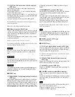
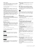
HDCU1000 Front Panel
a
Red tally indicator
Lights in red when this unit receives a red tally signal.
When the CALL button on the video camera, the MSU-
900 series Master Setup Unit, the RCP-700 series Remote
Control Panel, etc. is pressed, this indicator will go out if
previously lit, and light up if previously off.
You can attach the supplied number plate here.
b
Green tally indicator
Lights in green when this unit receives a green tally signal.
You can attach the supplied number plate here.
c
MIC (microphone) switch
Press to turn the intercom microphone on and off.
d
INTERCOM level control
Turn to adjust the input level of the intercom.
e
CABLE ALARM indicators
SHORT (red):
Lights in red when the power supply cord
of an optical fiber cable is short to external, or two
power supply cords are short.
Power isn’t input to the camera when this indicator
lights.
OPEN (red):
Lights in red when a camera isn’t connected
to the CAMERA connector on the rear panel of this
unit via an optical fiber cable.
Flashes when the connection status of an optical fiber
cable is bad.
f
MAIN POWER switch and indicator
Turns the entire camera system on and off, including this
unit, the video camera, and the RCP-700 series Remote
Control Panel connected to the REMOTE connector of this
unit.
Press the “
?
” side to turn the camera system on, and the
“
a
” side to turn it off.
The indicator lights when the power switch is turned on.
g
CAMERA POWER switch and indicator
Turns the video camera on and off when the MAIN
POWER switch is turned on.
Press the “
?
” side to turn on the video camera and the “
a
”
side to turn it off.
When the CAM PW button of the remote control panel
connected to this unit is set to off,
you can’t turn on the video camera with this switch only.
1
Red tally indicator
2
Green tally indicator
3
MIC switch
4
INTERCOM level control
5
CABLE ALARM indicators
6
MAIN POWER switch and indicator
7
CAMERA POWER switch and indicator
8
INTERCOM connector


