.
IM/HDCU1000 Series
1-13 (E)
A
B
C
D
E
F
G
H
J
1
2
3
4
5
D4
D411
S403 S404 S405
D412
S410
S409
S408
S407
S406
S419
S418
S402
S401
S420
S416
D409
D410
S411
RV702
RV701
S103
S104
S101
S102
S413
S412
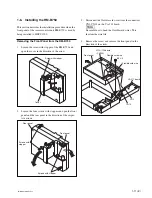
AT-167 (Side A)
AT
REF IN
UN
LOCK
H PHASE
REFERENCE
HD
RMT
SD
ADV
DELAY
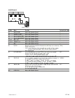
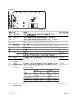
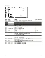
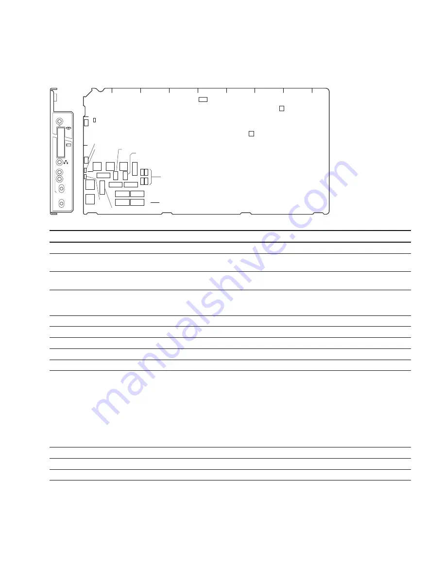
1-7. On-board Indicator/Switch/Volume Functions
AT-167 board
Ref.No. Name
Function
Factory default setting
D4
POWER
(Green) Illuminates when the power inside the AT board starts up correctly.
_
D409
REF IN
(Green) Illuminates when the reference signal is input and the external
_
synchronous mode is established.
D410
UNLOCK
(Red) Illuminates when CCU cannot lock the external reference signal in the
_
external synchronous mode.
D411
MS-LED
(Red/green) Displays the access status to the Memory Stick.
_
Red light: Accessing the Memory Stick. Do not remove the Memory Stick.
Green light: The inserted Memory Stick can be removed.
D412
LAN-LED
*
(green) Illuminates when communication is in progress via the Ethernet connector.
_
S101
PRTCT
Factory use
ON
S102
DEBUG
Factory use
OFF
S103
URA
Factory use
OFF
S104
DEBUG
Factory use
OFF
S401
REFERENCE
Select the type of the synchronous signal to be connected to the REFERENCE
REMOTE
terminal of this unit with this switch.
HD : Synchronizes (SYNC) with the HD reference signal.
(Input frame frequency is automatically adjusted.)
REMOTE : Controls from the remote panel such as that on MSU.
SD : Synchronizes (SYNC) with the SD reference signal (BB).
The VBS OUT signal synchronizes (SC) when HKCU1001/1003 is installed.
When the setting of the switch and the type of the input synchronous signal does
not match, the LED of D410 (UNLOCK) illuminates.
S402
H-PHASE
Adjusts the H-phase.
S403
H-Phase (STEP)
Adjusts the level phase for the reference signal in steps.
8
S404
V-Phase
Adjusts the vertical phase for the reference signal in line steps.
8
*
: This function has been added to software V1.10 and the later versions.

