2-16 (E)
.
IM/HDCU1000 Series
2-2. Setting the System Format
2-2-1. Setting the Multi-Format
Sets the format of the signal that is output from
HDCU1000/1080/1500.
Normally the format is set from the MSU connected
outside or from MULTI FORMAT on page “S02” of the
system menu in the HDCU1000/1080/1500. However, it
can also be set with the switches on the AT-167 board.
1. Setting the HD-SDI output
Sets the format of the signal that is output as the HD-SDI
signal. At the same time, this setting becomes the shooting
mode of the camera.
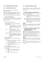
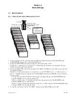
(1) Set the field frequency coefficient.
Setup switch : S420 on the AT-167 board (Factory
setting : REMOTE)
1.001 :
Set the field frequency to 1/1.001 times
(Set the field frequency to 1.001 when
using NTSC (525/60) signal in the SD
system.)
1.000 :
Set the field frequency to 1 time.
(Set the field frequency to 1.000 when
using PAL (625/50) signal in the SD
system.)
REMOTE : Set from the MSU connected outside or
from MULTI FORMAT on page “S02”
of the system menu in the HDCU1000/
1080/1500.
(2) Set the field frequency.
Setup switch: S418 on the AT-167 board (Factory
setting: 60 V)
60 V : When the 60 field HD signal or the NTSC
SD (525/60) signal is used.
50 V : When the 50 field HD signal or the PAL SD
(625/50) signal is used.
48 V : Only the 24PsF progressive system is
supported.
(3) Set the shooting mode of the camera.
Setup switch : S419 on the AT-167 board (Factory
setting : INTR)
I :
When shooting with interlacing system.
PsF : When shooting with progressive (PsF)
system.
720 : When shooting with 720P system.
2-2-2. Setting the Reference Input
Normally the reference input is set from MSU connected
outside. However, it can also be set by the switch on the
AT-167 board.
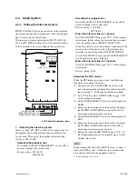
1. Setting the reference input signal format
Setup switch : REFERENCE switch (S401) on the AT-167
panel (Factory setting : REM)
HD : When the HD analog ternary SYNC is used.
(This unit supports the frame frequency auto-
matically.)
SD :
When the BB (black burst) signal of SD is used.
REM : When the reference is set from GEN-LOCK
PHASE on page “S01” of the system menu in
the HDCU1000/1080/1500 or from the MSU
connected outside.
n
When a position other than REM is set, all of the REFER-
ENCE settings including the phase adjustment must be
locally set.
2. Inputting the sub reference signal (when the
HKCU1003/VDA-64B is installed)
(HDCU1000/1500 only)
When the EN-159B board and VDA-64B board of the
HKCU1003 are installed in the optional slots, the sub
reference signal is input and the frame sequences of the
24PsF signal and the 60i signal can be locked.
Input the frame frequency signal that is different from the
main reference signal for the sub reference signal.
n
When the sub reference is not input, the pulse gate signal
of the frame sync is output from the loop-through output
terminal.
The frame sequence between multiple CCUs can be locked
if you connect this signal to the sub reference input of
other CCUs.

