background image

3-20 (E)

.

 IM/HDCU1000 Series

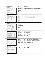
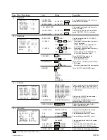
 <COLOR BAR>     ?C00 TOP

 HD-BAR
  SEL  MF-SMPTE(100%.Q)
  MF-CB   : MODIFY
  SLOPE   : WIDE

 SD-BAR   : SMPTE   : ENB

 BAR-CHARA:OFF

 GRAY:  ON

Page

C00

Menu / Menu Image

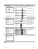
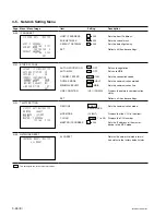
COLOR BAR

Item

HD-BAR

SEL
MF-CB

SLOPE

SD-BAR

BAR-CHARA

GRAY

Setting

HD-BARS FORMAT (

*

4)

MODIFY /EVEN

WIDE /NARROW

SD-BARS FORMAT (

*

5)

ENB /DSB

OFF /ON

OFF/ ON

Description

Sets the color bar for the HD output.

  Sets the type of color bar signal.
  Selects MF-CB width.

Sets the slope (width) of the color bar
signal.

Sets the color bar for the SD output.

ENB :

Outputs CB for SD.

DSB :

Changes HD-CB to SD signal and
outputs it.

Turns ON/OFF the BARS CHARAC-
TERS function that superimposes
characters on the color bar signal.

Turns ON/OFF the GRAY function.
ON : Outputs a gray screen when there

is a signal error, or when the
power to the camera is off.

OFF : Outputs the CB signal.

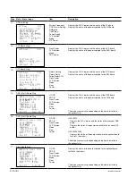
3-4-2. When V1.10 or a later version of the software

: The settings in the box are default values.

(

*

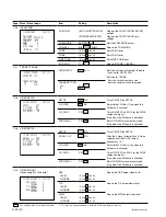
4) HD-BARS FORMAT

BAR 16:9 (100%)
BAR 16:9 (75%)
SMPTE 16:9 (BLACK)
SMPTE 16:9 (

_

I/Q)

BAR 4:3 (100%)
BAR 4:3 (75%)
SMPTE 4:3 (BLACK)
SMPTE 4:3 (

_

I/Q)

MF-ARIB (75%)
MF-ARIB (100%)
MF-ARIB (

+

I)

MF-SMPTE (

_

I, Q)

MF-SMPTE (75%, Q)
MF-SMPTE (100%, Q)
MF-SMPTE (

+

I, Q)

HD-CUSTOM
SDI CHECK FIELD
Y -RAMP
Y/C-RAMP
HD-CUSTOM2

(

*

5) SD-BARS FORMAT

SMPTE
EIA
FULL
95%
NTSC100%
Y/C-RAMP
Y -RAMP

Summary of Contents for HD Super Motion HKCU1001

Page 1: ...LLATION MANUAL 1st Edition Revised 4 Serial No 10001 and Higher HDCU1000 UC Serial No 30001 and Higher HDCU1000 J Serial No 40001 and Higher HDCU1000 CE Serial No 50001 and Higher HDCU1000 E3 Serial No 60001 and Higher HDCU1000 E2 Serial No 50001 and Higher HDCU1080 CN Serial No 10001 and Higher HDCU1500 SY Serial No 30001 and Higher HDCU1500 J ...

Page 2: ...ente uniquement Attention when the product is installed in Rack 1 Prevention against overloading of branch circuit When this product is installed in a rack and is supplied power from an outlet on the rack please make sure that the rack does not overload the supply circuit 2 Providing protective earth When this product is installed in a rack and is supplied power from an outlet on the rack please c...

Page 3: ...re V1 10 or later version is used with the system connection mode via Ethernet set 3 3 E Manual Structure Purpose of this manual 3 E Related manuals 3 E Trademarks 3 E 1 Installation Overview 1 1 Checking the ROM and Software Version 1 1 E 1 2 Connectors and Cables 1 2 E 1 2 1 Connector Input Output Signal 1 2 E 1 2 2 Cable Wiring Diagram 1 6 E 1 2 3 Connection Connectors 1 7 E 1 2 4 Note when Con...

Page 4: ...nection mode via Ethernet set 3 4 E 3 2 2 When software V1 10 or later version is used with the system connection mode via Ethernet set 3 8 E 3 3 System Menu 3 12 E 3 4 Configuration Menu 3 16 E 3 4 1 When version of the software prior to V1 10 3 16 E 3 4 2 When V1 10 or a later version of the software 3 20 E 3 5 Network Setting Menu 3 26 E ...

Page 5: ...al Available on request This manual intended for use by trained system and service engineers describes service overview and the circuit overview the main part replacements electrical alignment parts list semiconductor pin assignments block diagrams schematic diagrams board layouts required for parts level service For obtaining contact your local Sony Sales Office Service Center Part number 9 968 2...

Page 6: ......

Page 7: ...ce Service Center ROM Peripheral equipment Board Ref No ROM version MSU 700A 750 CPU 293 CPU 286 IC5 IC6 IC5 IC6 Ver 1 30 or higher MSU 900 CPU 396 IC18 IC31 Ver 1 02 or higher CNU 700 AT 89 or AT 89A IC4 IC5 Ver 3 20 or higher CNU 500 AT 100 IC4 IC5 Ver 2 80 or higher RCP 720 721 MPU 79 IC10 Ver 2 90 or higher RCP 730 731 MPU 79 IC10 Ver 2 90 or higher RCP 740 741 MPU 79 IC10 Ver 2 90 or higher R...

Page 8: ...lack burst signal 75 Z PROMPTER 1 2 BNC 1 0 V p p 75 Z OUTPUT SYNC BNC 0 3 V ternary SYNC 75 Z 0 3 V p p SD SYNC 75 Z selectable CHARACTER BNC 1 0 V p p 75 Z AES EBU BNC AES EBU format HDCU1500 SDI OUT 1 3 BNC Conforms to BTA S004B 0 8 V p p 75 Z 1 485 Gbps 1 4835 Gbps SMPTE 292M or Component serial signal 0 8 V p p 75 Z 270 Mbps SMPTE 259M RET 1 3 IN BNC Conforms to BTA S004B 1 485 Gbps 1 4835 Gb...

Page 9: ...OUT BNC B Y 0 7 V p p 75 Z NTSC SETUP ON when outputting 75 color bar 0 525 V p p 75 Z PAL when outputting 75 color bar B 0 7 V p p 75 Z WF REMOTE D sub 15P Female HDCU1000 1080 _ _ _ _ _ EXT VIEW _ _ _ _ _ No Signal Specifications 1 NC No connection 2 NC No connection 3 NC No connection 4 NC No connection 5 RECALL2 G LOW ACTIVE 6 RECALL3 B 7 RECALL1 R 8 RECALL4 SEQ 9 GND 10 NC No connection 11 NC...

Page 10: ...V PULL UP 6 IN6 GND 5 V OPEN 47 kZ 5 V PULL UP 7 IN7 GND 5 V OPEN 47 kZ 5 V PULL UP 8 IN8 GND 5 V OPEN 47 kZ 5 V PULL UP 9 GND 10 OUT1 0 5 V 1 kZ 11 OUT2 0 5 V 1 kZ 12 OUT3 0 5 V 1 kZ 13 OUT4 0 5 V 1 kZ 14 OUT5 0 5 V 1 kZ 15 OUT6 0 5 V 1 kZ 15 9 1 8 1 2 3 MIC1 MIC2 XLR 3P Male _ _ _ _ _ EXT VIEW _ _ _ _ _ 0 dBu 0 775 Vrms No Signal Specifications 1 MIC OUT G 0 dBu _20 dBu 2 MIC OUT X Selectable wi...

Page 11: ...Refer to the right column ON OFF IN 9 GND GND for 5 5 V 10 TALLY OUT R G TALLY OUT ON GND Max 30 mA IN 11 PREVIEW OUT ON GND 47 kZ 5 V PULL UP 12 ASPECT REMOTE L REMOTE ON OFF 13 ASPECT CONT1 3 Refer to the right column 14 CTL CONT2 15 MIC2 GAIN CONT 2 Refer to the right column ON OFF IN 15 9 1 8 1 CHU MIC 1 2 AMP GAIN CONT0 CONT1 CONT2 CHU MIC AMP GAIN H H H 60 dB L H H 50 dB H L H 40 dB L L H 30...

Page 12: ...RECEIVE 0 dBu BALANCED 16 PROD G GND for PROD 17 PROD T X IN PROD SYSTEM TALK 18 PROD T Y IN 0 dBu BALANCED 19 PGM2 X IN _20 dBu 0 dBu 20 PGM2 Y IN Selectable with 21 PGM2 G IN S503 AVP board 22 AUX4 23 AUX5 24 G TALLY X IN ON 24 Vdc TTL H SHORT 25 G TALLY Y IN OFF 0 Vdc TTL L OPEN 25 14 1 13 INTERCOM 5P Female _ _ _ _ _ EXT VIEW _ _ _ _ _ 0 dBu 0 775 Vrms No Signal Specifications 1 INCOM T IN Y _...

Page 13: ...e used for this camera system the connection connectors specified in this manual must be used in order to comply with the limits for EMC regulations 1 2 4 Note when Connecting CAMERA Connector Before connecting the unit to the camera adaptor clean the following optical contact blocks For the cleaning procedure refer to Section 1 12 Clean ing of Connector Cable CAMERA connector of the unit CCU conn...

Page 14: ...CE 50001_51999 HDCU1080 CN HIF 26 board 14001 and Higher HDCU1000 UC 41001 and Higher HDCU1000 CE 52001 and Higher HDCU1080 CN 50001 and Higher HDCU1000 E3 60001 and Higher HDCU1000 E2 EN 159A board HKCU1001 EN 159B board HKCU1003 DRX 5 board HKCU1005 VDA 64A board HKCU1001 VDA 64A board HKCU1003 VDA 64B board HKCU1003 VDA 64C board HKCU1003 HIF 26 board HKCU1005 DU 390 board HDCU1080 only HKCU100...

Page 15: ... HKCU1005 VDA 64A board HKCU1001 VDA 64A board HKCU1003 VDA 64B board HKCU1003 VDA 64C board HKCU1003 HIF 26 board HKCU1005 1 CN 2678 board 2 AU 303 303G board 3 AT 167 board 4 AVP 6 board 5 DTX 5 board 6 DRX 5 board 7 VIF 34B 34BG board 8 ADO 10 10G board 9 SDI 87 87G board HIF 27 board MB 1072 1072G board CN 2677 2677G board CN 2676 board CN 2675 2675G board SDP 12 board CNB 22 22G board ...

Page 16: ...tach the front panel in reverse order of step 1 Front panel Screws with stopper 1 5 2 Removing Installing the Front Panel HDCU1500 1 Loosen the two screws with stopper and open the front panel in the direction of the arrow 2 Reattach the front panel in reverse order of step 1 Screw with stopper Screw with stopper Front panel 1 4 External Dimensions 1 4 1 HDCU1000 1080 1 4 2 HDCU1500 424 410 465 48...

Page 17: ...en the four screws with stopper and open the front panel and the rear panel in the direction of the respec tive arrows 3 Disconnect the flexible card wires from the connectors CN2 CN14 on the VA 211 board n Be careful not to bend the flexible card wires This shortens the wire life 4 Remove the screw and remove the front panel in the direction of the arrow Cover Screw with stopper Front panel Rear ...

Page 18: ... Installing the Front Panel to the Unit 5 Turn off the power and disconnect the plug from the outlet 6 Open the front panel of the unit Refer to Section 1 5 2 7 Remove the screw 8 Slide the front panel in the direction of the arrow to extract the pin from the potbellied hole and remove the front panel 9 Insert the pin into the potbellied hole of the front panel of the RM B750 removed in step 4 and...

Page 19: ...he inserted Memory Stick can be removed D412 LAN LED green Illuminates when communication is in progress via the Ethernet connector _ S101 PRTCT Factory use ON S102 DEBUG Factory use OFF S103 URA Factory use OFF S104 DEBUG Factory use OFF S401 REFERENCE Select the type of the synchronous signal to be connected to the REFERENCE REMOTE terminal of this unit with this switch HD Synchronizes SYNC with...

Page 20: ...ut from MSU when the ASPECT switching from outside D Sub is valid 5 Not used 6 CNU RM For setting the priority of remote device on HDCU1500 hen the OFF Front PNL RM RM B750 is installed ON Front PNL RM has priority OFF Device connected to the Rear RM CMD connector has priority 7 RCP PX ENB DIS Sets the monitor selection control method for PIX OUT by RCP OFF ON Only WF can be controlled from RCP OF...

Page 21: ...sed _ 7 Not used _ 8 CO AX DIS ENB Factory use OFF S409 CCU NO CCU No setting _ 1 to 4 S409 4 to 1 1 digit BCD OFF ALL 5 to 8 S409 8 to 5 10 digit BCD OFF ALL S410 HD SD DLY Video phase setting between HD and SD LINE DLY Sets the phase difference delay time between HD signal and SD signal output from CCU Can switch the delay settings among 0 DLY LINE DLY and FRAME DLY 0 DLY Same phase mode of HD S...

Page 22: ...the main video format of CCU is set as in the following table The output transmission format of CHU is set in the same way Refer to the table below S420 1001 RMT 1000 Operation clock frequency setting REMOTE 1 001 Sets the field frequency of CCU to 59 94 29 97 23 98 Hz 1 000 Sets the field frequency of CCU to 60 50 25 24 Hz REMOTE Can be set from MSU Can also perform remote local setting of video ...

Page 23: ... between a voice and PGM for the front intercam reception OFF PGM OFF The FP INCOM reception becomes a voice PGM ON The FP INCOM reception becomes PGM Switching of receipt is valid when the INCOM MIX switch is set to OFF S4 FRONT MIC Sets the microphone input level according to the type of headset microphone to CARBON be connected to the INCOM connector on the front panel DYNAMIC Dynamic microphon...

Page 24: ...F microphone connected to the INCOM connector on the front panel and receiving audio PGM program audio of the producer line or engineer line MIC ON Turns ON the headset microphone MIC OFF Turns OFF the headset microphone PGM The program audio is output to the INCOM connector on the front panel S5 FRONT MIC Sets the microphone input level according to the type of headset microphone CARBON to be con...

Page 25: ...is off and turns off when it is on S2 Not used 0 S3 Not used 0 S4 MODE 1 7 Factory use OFF ALL 8 Set this to ON when upgrading the PLD IC208 IC409 version of the SDP 12 OFF board Be sure to set the switch to OFF after the upgrade is completed S11 R TALLY Set according to the signal standard of the R TALLY signal input to the INTERCOM CONTACT POWER CONTACT TALLY PGM connector on the rear panel For ...

Page 26: ...PGM2 IN Sets the input level of the system PGM analog 0 dB 0dB When the input level of the system is 0 dBu _20dB When the input level of the system is _20 dBu S602 PROD SEL Selects the intercom system of the producer line 4W S600 PROD SEL2 RTS S603 ENG SEL Selects the intercom system of the engineer line 4W S601 ENG SEL2 RTS RV500 MIC1 LEV RV501 MIC2 LEV RV600 PROD 2WIRE CANCEL RV601 ENG 2WIRE CAN...

Page 27: ...en Illuminates when the Main output is 1080 24PsF 23 98PsF _ Blinks when the format setting is defective D3 POWER Illuminates when the power to the DRX board has correctly started _ S1 MODE2 Not used 0 S2 MODE1 1 CLEAN Turns on or off the character MIX function of SDI monitor output 3 4 OFF OFF Normal SDI monitor output ON Keeps the characters and the markers of the SDI monitor output 3 4 turned o...

Page 28: ... signal must be turned on and the character signals from the rest of the DRX boards must be turned off Set only the first DRX board to ON and the rest of the DRX boards to OFF Set only the first board to ON and the rest to OFF RV1 MONI LEV Adjusts the output level of the character monitor signal Ref No Name Function Factory default setting S401 1 8 Factory Use Only _ OFF ALL S402 Factory Use Only ...

Page 29: ...aracters to the Monitor output OFF DISP Displays the DISP page that displays the CCU status OFF Turn off the mixing of characters MENU Displays the CCU MENU page S604 CHARACTER Cancels or executes MENU operations while CCU MENU is displayed _ CANCEL Use to cancel ENTER Use to execute the content S605 CHARACTER Changes the page setting of the character DISP or MENU mixed to _ the Monitor output wit...

Page 30: ...veform monitor the display interval can be adjusted RV303 VBS GAIN Adjusts the video level of the VBS output RV304 PIX GAIN Adjusts the video level of the PIX output RV305 WF GAIN Adjusts the video level of the WF output RV501 Y GAIN UC Adjusts the video level of the Y output RV502 R Y GAIN Adjusts the video level of the R Y output RV503 B Y GAIN Adjusts the video level of the B Y output RV504 R Y...

Page 31: ...ors on the new power supply unit to the settings shown in the diagram 7 Confirm if the CAMERA fuse of the replacement power supply unit adapts to the working power supply voltage If not replace it with the one adapting to the working power supply voltage Refer to Section 1 8 2 n If the rating of the fuse doesn t adapt to the working power supply voltage the safety can not be ensured So the CAMERA ...

Page 32: ...ng it in the direction of arrow B to lock the fuse holder Fuse holder B C Flat blade screwdriver 1 8 2 Replacing the Fuse HDCU1000 1080 w The components marked are critical to safe operation If you replace with parts other than the specified ones a fire or electric shock may result from that Replacement Part MAIN fuse Part Fuse 3 15 A 250 V Part No 1 576 230 51 CAMERA fuse For UC 100 to 120 V Part...

Page 33: ...6 3 3 2 3 EN 159B 3 VDA 64A 4 4 VDA 64C 5 5 6 6 3 4 2 3 EN 159B 3 VDA 64B 4 4 VDA 64C 5 5 6 6 1 The number in parentheses in the rear side slot column indicates the slot number for HDCU1080 2 This is the installation procedure of the option board for HDCU1000 When installing two option boards No Front side Rear side slot Board name slot 1 Board name 4 3 DRX 5 3 2 HIF 26 4 DRX 5 4 3 HIF 26 5 5 4 6 ...

Page 34: ... 5 VDA 64B 6 6 VDA 64C When installing four option boards No Front side Rear side slot Board name slot 1 Board name 13 3 DRX 5 3 2 HIF 26 4 DRX 5 4 3 HIF 26 5 EN 159A 5 4 VDA 64A 6 EN 159A 6 5 VDA 64A 14 1 2 3 DRX 5 3 HIF 26 4 DRX 5 4 HIF 26 5 EN 159A 5 VDA 64A 6 EN 159B 6 VDA 64A 14 2 2 3 DRX 5 3 HIF 26 4 DRX 5 4 HIF 26 5 EN 159A 5 VDA 64A 6 EN 159B 6 VDA 64B 1 The number in parentheses in the re...

Page 35: ...2 EN 159B 2 VDA 64A 3 3 3 2 2 EN 159B 2 VDA 64B 3 3 3 3 2 EN 159B 2 VDA 64A 3 3 VDA 64C 3 4 2 EN 159B 2 VDA 64B 3 3 VDA 64C When installing two option boards No Front side Rear side slot Board name slot Board name 4 2 DRX 5 2 HIF 26 3 DRX 5 3 HIF 26 5 2 DRX 5 2 HIF 26 3 EN 159A 3 VDA 64A 6 1 2 DRX 5 2 HIF 26 3 EN 159B 3 VDA 64A 6 2 2 DRX 5 2 HIF 26 3 EN 159B 3 VDA 64B 7 2 EN 159A 2 VDA 64A 3 EN 15...

Page 36: ...e slot fix the option board with two screws 1 10 Installing the Option Boards 1 10 1 HDCU1000 Front side 1 Turn off the power and unplug the power cord from the outlet 2 Remove the front panel Refer to Section 1 5 1 3 Insert the option board into the blank slot n Check that the option board is securely connected to the motherboard MB 1071 board Rear side When there are four slots Remove the two sc...

Page 37: ...rting the option board into the slot fix the option board with two screws 1 10 2 HDCU1080 Front side 1 Turn off the power and unplug the power cord from the outlet 2 Remove the front panel Refer to Section 1 5 1 3 Insert the option board into the blank slot n Check that the option board is securely connected to the motherboard MB 1071 board Rear side When there are four slots Remove the two screws...

Page 38: ...board is securely connected to the motherboard MB 1072 board 3 Fix the option board with the two screws removed at step 1 1 10 3 HDCU1500 Front side 1 Turn off the power and unplug the power cord from the outlet 2 Open the front panel Refer to Section 1 5 2 3 Insert the option board into the blank slot n Check that the option board is securely connected to the motherboard MB 1072 board Front board...

Page 39: ...nit w Fix the rack on the floor If the rack falls due to the weight of the equipment it may cause death or serious injury To prevent the rack from falling or moving be sure to fix the rack on the floor Do not install at a height of 1 m or higher from the floor If the rack falls it may cause death or serious injury When installing the unit be sure to fix the rack on the floor and be careful not to ...

Page 40: ...front bracket slide the mid member until the screw holes in the cabinet member are visible through the hole in the mid member as shown below When attaching the rear bracket adjust the position of the bracket with the rack depth 4 Attach the front and rear brackets to the outside of the rack temporarily using the eight screws B5 x 8 12 7 31 75 12 7 31 75 31 75 Rack front Rack rear B5 x 8 B5 x 8 Fro...

Page 41: ...refully 5 While pressing the stoppers of the inner rails slide the inner rails fully into the outer rails and push the unit into the rack slowly 6 After confirming that the unit can be moved smoothly tighten the screws B5 x 8 secured temporarily in the step 4 n When securing the front brackets to the rack by screws pull the unit out of the rack about 20 cm 8 inches and fasten the screws of the fro...

Page 42: ...following steps Tools Required Alignment sleeve remover HC 001 for female connector Sony P N J 6480 010 A or DCC 91 312 5LA manufactured by Lemo or equivalent n Insert the shorter nose end when removing installing the alignment sleeve Grasp not the shock absorber portion of the remover but the handle in use Alcohol Cotton swabs commercially available n Use a cotton swab whose diameter is about 4 m...

Page 43: ...ary expose the contacts by removing the adapter in advance Proceed as follows 1 Loosen the adapter pin in the center of the connector by turning it counterclockwise with a screwdriver and pull the adapter pin in the direction of the arrow to remove the adapter from the connector n If no screwdriver is available use the plate supplied with the connector cap 2 Clean the tip of the white optical cont...

Page 44: ......

Page 45: ...rame reference input output VDA 64B Component video signal output VDA 64C HKCU1005 SDI Output Expansion Unit DRX 5 SDI Output HIF 26 HKCU1003 is the option board for HDCU1000 It is not used for HDCU1080 n Regarding the installation of the optional boards refer to 1 10 in INSTALLATION MANUAL The difference of the rear panel and the system connections The rear panel is different according to the ser...

Page 46: ...d combinations Front side Rear side System configuration slot Board name slot Board name 1 Standard HD SD system 3 _ 3 _ 4 _ 4 _ 5 _ 5 _ 6 _ 6 _ 2 Standard HD SD system 3 EN 159A 3 VDA 64A SD analog encoder 4 _ 4 _ HKCU1001 5 _ 5 _ SD analog I F added 6 _ 6 _ 3 Standard HD SD system 3 DRX 5 3 HIF 26 Multi interface 4 EN 159B 4 VDA 64B SDI output expansion 5 _ 5 _ HKCU1003 1005 6 _ 6 _ HD SD Film L...

Page 47: ...r HD SDI Monitor CNU 700 HD SDI RETURN SIGNAL HD SD SDI SIGNAL SD SDI RETURN SIGNAL REFERENCE SIGNAL HD or SD PROMPTER SIGNAL SYNC OUT HD or SD HD SDI RETURN SIGNAL HD SD SDI SIGNAL Next HDCU1000 Terminated at 75 Z SD REFERENCE SIGNAL SD SDI RETURN SIGNAL SYNC OUT HD or SD SD ANALOG VIDEO SIGNAL Standard system without option ...

Page 48: ...PIX OUT WF OUT VBS VDA A 1 2 PIX OUT WF OUT VBS HD SD SDI SIGNAL HD SDI RETURN SIGNAL ANALOG COMPOSITE VIDEO SIGNAL SD SDI RETURN SIGNAL ANALOG RETURN SIGNAL REFERENCE SIGNAL HD or SD PROMPTER SIGNAL SYNC OUT HD or SD HD SD SDI SIGNAL Next HDCU1000 Terminated at 75 Z SD REFERENCE SIGNAL SD SDI RETURN SIGNAL HD SDI RETURN SIGNAL ANALOG RETURN SIGNAL SYNC OUT HD or SD SD ANALOG VIDEO SIGNAL ANALOG C...

Page 49: ...N PIX OUT WF OUT OUT VDA B FRAME REF IN PIX OUT WF OUT OUT VDA B HD SD SDI SIGNAL HD SDI RETURN SIGNAL SUB REFERENCE SIGNAL SD SDI RETURN SIGNAL REFERENCE SIGNAL PROMPTER SIGNAL SYNC OUT HD SD SDI SIGNAL Next HDCU1000 Terminated at 75 Z SD REFERENCE SIGNAL HD SDI RETURN SIGNAL SD SDI RETURN SIGNAL SYNC OUT SD ANALOG VIDEO SIGNAL 3 Standard HD SD system multi interface unit HKCU1003 SDI output expa...

Page 50: ...OUT VBS HD SD SDI SIGNAL ANALOG RETURN SIGNAL ANALOG RETURN SIGNAL REFERENCE SIGNAL PROMPTER SIGNAL SYNC OUT SD Next HDCU1000 Terminated at 75 Z SD REFERENCE SIGNAL SYNC OUT SD SD ANALOG VIDEO SIGNAL ANALOG COMPOSITE VIDEO SIGNAL ANALOG COMPONENT VIDEO SIGNAL HD SD SDI SIGNAL ANALOG COMPOSITE VIDEO SIGNAL ANALOG COMPONENT VIDEO SIGNAL 4 Standard HD SD system multi interface unit HKCU1003 Analog NT...

Page 51: ...50 751 CNU 700 MSU 900 950 SD Analog Monitor Example of board combinations Front side Rear side System configuration slot Board name slot Board name 1 Standard HD SD system 2 _ 2 _ 3 _ 3 _ 4 _ 4 _ 5 _ 5 _ 2 Standard HD SD system 2 EN 159A 2 VDA 64A SD analog encoder 3 _ 3 _ HKCU1001 4 _ 4 _ SD analog I F added 5 _ 5 _ 3 Standard HD SD system 2 DRX 5 2 HIF 26 SDI output expansion 3 _ 3 _ HKCU1005 4...

Page 52: ...580 HDC1580 CNU 700 HD SD SDI SIGNAL REFERENCE SIGNAL HD or SD PROMPTER SIGNAL SYNC OUT HD or SD HD SD SDI SIGNAL Next HDCU1080 Terminated at 75 Z SD REFERENCE SIGNAL SYNC OUT HD or SD SD ANALOG VIDEO SIGNAL HD SDI RETURN SIGNAL SD SDI RETURN SIGNAL HD SDI RETURN SIGNAL SD SDI RETURN SIGNAL Standard system without option ...

Page 53: ...UT WF OUT VBS VDA A 1 2 PIX OUT WF OUT VBS HD SD SDI SIGNAL ANALOG COMPOSITE VIDEO SIGNAL HD SD SDI SIGNAL Next HDCU1080 Terminated at 75 Z SD REFERENCE SIGNAL SD ANALOG VIDEO SIGNAL ANALOG COMPOSITE VIDEO SIGNAL HD SDI RETURN SIGNAL SD SDI RETURN SIGNAL ANALOG RETURN SIGNAL REFERENCE SIGNAL HD or SD PROMPTER SIGNAL SYNC OUT HD or SD SD SDI RETURN SIGNAL HD SDI RETURN SIGNAL ANALOG RETURN SIGNAL S...

Page 54: ...1 3 2 4 SDI OUT HD SD SDI SIGNAL HD SD SDI SIGNAL Next HDCU1080 Terminated at 75 Z SD REFERENCE SIGNAL SD ANALOG VIDEO SIGNAL HD SDI RETURN SIGNAL SD SDI RETURN SIGNAL REFERENCE SIGNAL PROMPTER SIGNAL SYNC OUT HD SDI RETURN SIGNAL SD SDI RETURN SIGNAL SYNC OUT 3 Standard HD SD system SDI output expansion unit HKCU1005 HD SD SDI system ...

Page 55: ...T OPEN CAM MAIN CABLE ALARM INCOM POWER 1 ENG PGM ON MIC OFF PRIV HDCU1500 HKCU1001 HKCU1003 HKCU1005 HD CAMERA CONTROL UNIT PROD SHORT OPEN CAM MAIN CABLE ALARM INCOM POWER 1 ENG PGM ON MIC OFF PRIV Example of board combinations Front side Rear side System configuration slot Board name slot Board name 1 Standard HD SD system 2 _ 2 _ 3 _ 3 _ 2 Standard HD SD system 2 DRX 5 2 HIF 26 SD analog encod...

Page 56: ... SD SDI SIGNAL REFERENCE SIGNAL HD or SD SYNC OUT HD or SD SYNC OUT HD or SD HD SD SDI ANALOG RETURN SIGNAL PROMPTER SIGNAL Next HDCU1500 Terminated at 75 Z SD REFERENCE SIGNAL SD ANALOG VIDEO SIGNAL HD SD SDI SIGNAL HD SD SDI ANALOG RETURN SIGNAL 1 Standard HD SD system Standard system without option ...

Page 57: ... OUT WF OUT VBS VDA A 1 2 PIX OUT WF OUT VBS REFERENCE SIGNAL HD or SD SYNC OUT HD or SD SYNC OUT HD or SD HD SD SDI ANALOG RETURN SIGNAL PROMPTER SIGNAL Next HDCU1500 Terminated at 75 Z SD REFERENCE SIGNAL SD ANALOG VIDEO SIGNAL HD SD SDI SIGNAL ANALOG COMPOSITE VIDEO SIGNAL HD SD SDI ANALOG RETURN SIGNAL ANALOG COMPOSITE VIDEO SIGNAL HD SD SDI SIGNAL 2 Standard HD SD system SD analog encoder HKC...

Page 58: ...FRAME REF IN PIX OUT WF OUT OUT VDA B FRAME REF IN PIX OUT WF OUT OUT VDA B REFERENCE SIGNAL SYNC OUT SYNC OUT HD SD SDI ANALOG RETURN SIGNAL PROMPTER SIGNAL Next HDCU1500 Terminated at 75 Z SD REFERENCE SIGNAL SD ANALOG VIDEO SIGNAL HD SD SDI SIGNAL SUB REFERENCE SIGNAL HD SD SDI ANALOG RETURN SIGNAL HD SD SDI SIGNAL 3 Standard HD SD system multi interface unit HKCU1003 SDI output expansion unit ...

Page 59: ...NCE SIGNAL SYNC OUT SD SYNC OUT SD HD SD SDI ANALOG RETURN SIGNAL HD SD SDI SIGNAL PROMPTER SIGNAL Next HDCU1500 Terminated at 75 Z SD REFERENCE SIGNAL SD ANALOG VIDEO SIGNAL HD SD SDI ANALOG RETURN SIGNAL ANALOG COMPONENT VIDEO SIGNAL ANALOG COMPONENT VIDEO SIGNAL HD SD SDI SIGNAL HD SD SDI ANALOG COMPOSITE VIDEO SIGNAL ANALOG COMPOSITE VIDEO SIGNAL 4 Standard HD SD system multi interface unit HK...

Page 60: ...h S419 on the AT 167 board Factory setting INTR I When shooting with interlacing system PsF When shooting with progressive PsF system 720 When shooting with 720P system 2 2 2 Setting the Reference Input Normally the reference input is set from MSU connected outside However it can also be set by the switch on the AT 167 board 1 Setting the reference input signal format Setup switch REFERENCE switch...

Page 61: ... series and the INCOM SELECT switch on the front panel of the unit When the intercom line is 2 channels Set 2CH at INCOM CH on page C05 of the configu ration menu Factory setting 2CH Adjusting the RTS cancel When the RTS intercom system is used the following adjustment also needs to be made 1 Connect a headset to the INCOM connector on the front and perform the procedure described in the follow in...

Page 62: ...m line to be connected to the INCOM connector Use the switch on the front panel to select the intercom line to be connected to the INCOM connector on the front as follows When connecting to the producer line Set the INCOM SELECT switch to PROD When connecting to the engineer line Set the INCOM SELECT switch to ENG When connecting only a camera Set the INCOM SELECT switch to PRIV When this position...

Page 63: ...ollowing methods 1 Adjusting the microphone input gain to be set from MENU When the MIC REMOTE connector on the rear panel is connected to nothing or the levels of pin 8 MIC 1 and pin 15 MIC 2 of the MIC REMOTE connector are High the microphone input gain can be adjusted from CHU MIC GAIN on page C04 of the configuration menu Factory setting 60 dB 2 Adjusting the microphone input gain using the MI...

Page 64: ...y E F G H J S12 S11 S22 S32 S21 S31 R TALLY G TALLY U TALLY POWER CONTACT POWER TTL 1 2 3 4 5 6 0 7 8 50 5 1 2 3 4 5 6 1 7 8 61 6 1 2 3 4 5 6 2 7 8 72 7 1 2 3 4 5 6 3 7 8 83 8 1 2 3 4 5 6 4 7 8 94 9 Example of setting First digit Second digit Camera number 2 4 2 Setting the Camera Number System that does not use CNU 700 500 Use switch S409 on the AT 167 board to set the camera number Use switches ...

Page 65: ...NTERCOM TALLY PGM MIC OUT RCP CNU RCP CNU MIC REMOTE WF REMOTE WF MODE MIC OUTPUT MIC CONTROL and TALLY or WF MONITOR CONTROL WF MONITOR SEQ CONTROL MIC OUT MIC REMOTE or WF REMOTE WF MODE SWITCHER HDCU1000 1080 1 MSU WF MONITOR CONTROL 1 3 2 4 SDI OUT 1 3 2 4 SDI OUT 1 3 2 4 SDI OUT 1 3 2 4 SDI OUT FRAME REF IN PIX OUT WF OUT OUT VDA B VBS R R Y G Y B B Y VDA C 1 2 2 4 3 Connecting the Control In...

Page 66: ... 3 V p p sequence pulse 40 IRE 0 3 V p p Adjusting the Phase of the Sync Signal Adjust the phase of the output signal to match it with that of the reference signal Perform the adjustment using the switch on the AT 167 and EN 159 board HKCU1001 1003 panel of HDCU1000 1080 1500 The adjustment also can be performed on the maintenance menu of the MSU 900 950 How to adjust on the AT 167 board and EN 15...

Page 67: ...al 4 3 Letter box The HD video signal of 16 9 is inserted into the picture frame of 4 3 as it is and convert ed to the SD signal 4 3 The black level is inserted into the top and bottom of the picture Semi letter box Video signal as large as 15 9 14 9 or 13 9 is cut from the HD video signal is inserted into the picture frame of 4 3 and is convert ed to the SD signal 4 3 The black level is inserted ...

Page 68: ...hout changing the ratio Letter box 16 9 The 16 9 ratio picture is inserted into the 4 3 ratio picture without changing the ratio and is output in the SD SDI format Semi letter box 14 9 The picture that is cut out with the aspect ratio of 14 9 is inserted into the 4 3 ratio picture and is output in the SD SDI format Semi letter box 13 9 The picture that is cut out with the aspect ratio of 13 9 is i...

Page 69: ...hat it is within the specified level Measurement point WF OUT connector on the HDCU rear panel Specification A 100 1 IRE for NTSC A 700 7 mVp p for PAL for PAL for NTSC A A E F G H J A 1 2 3 4 5 RV305 1 2 5 4 Adjusting the Level of the VBS Signal only when HKCU1001 1003 is installed Adjust the level of the VBS signal output from HDCU1000 1080 1500 using the color bar signal Use the switch on the E...

Page 70: ...ement point PIX OUT connector on the VCS 700 Specification A 100 1 IRE for NTSC A 700 7 mV p p for PAL WFM 1 LEVEL control Each luminescent spot on the vector monitor must be within the 4 range WFM 1 CHROMA control R MG B CY G YL R MG CY G YL B for NTSC for PAL for PAL for NTSC A A Maintenance Menu Adjusting CAM SW Setting Auto Setup Exit Lens Adjusting VCS Adjusting SD Adjusting SuperMotion Setti...

Page 71: ...ignals in the sequen tial mode on the waveform monitor If the signal of the sequential mode is not normally displayed on the wave form monitor perform this adjustment When the waveform monitor is connected to HDCU1000 1080 1500 perform the adjustment using controls RV301 STAIR STEP POSITION and RV302 STAIR STEP LEVEL on the EN 159A 159B board of the HKCU1001 1003 When the VCS 700 is connected refe...

Page 72: ...ation A 100 1 IRE for NTSC A 700 7 mV p p for PAL How to adjust using the VCS 700 In the system with the MSU 900 950 CNU 700 or VCS 700 the video output signal of the unit can be checked on the waveform or vector monitor connected to the PIX A OUTPUT and PIX OUTPUT connectors of the VCS 700 Connect the PIX OUT connector of the VDA 64A 64B board to the PIX 1 connector of the VCS 700 Then perform ad...

Page 73: ...tors on the rear panel of the HDCU1000 1080 1500 Configure the setting using RETURN FORMAT on page S05 of the maintenance menu in MSU 900 950 or the system menu of the HDCU1000 1080 1500 n HDCU1500 only Although the HDCU1500 only allows RET inputs RET1 to 3 the signal input to the PROMPTER connector on the rear panel can be used as the RET4 signal However the input format is VBS only ...

Page 74: ......

Page 75: ...U open the front panel of HDCU1000 1080 1500 and use the CHARACTER switch CANCEL ENTER switch and _ switch on the DTX 5 board 2 Pressing the CHARACTER switch upward displays the status display menu of CCU Pressing the _ switch upward or downward _ changes the pages and another screen is displayed The page number zero is a blank page with no character 3 Pressing the CHARACTER switch downward displa...

Page 76: ...7 board to OFF 1 To operate the menu of CCU open the front panel of HDCU1000 1080 1500 and use the CHARACTER switch CANCEL ENTER switch and _ switch on the DTX 5 board 2 Pressing the CHARACTER switch upward displays the status display menu of CCU Pressing the _ switch upward or downward _ changes the pages and another screen is displayed The page number zero is a blank page with no character 3 Pre...

Page 77: ...n mode via Ethernet set Sets the switch S407 TEST SW5 on the AT 167 board to ON 1 To operate the menu of CCU open the front panel of HDCU1000 1080 1500 and use the CHARACTER switch CANCEL ENTER switch and _ switch on the DTX 5 board 2 Pressing the CHARACTER switch upward displays the status display menu of CCU Pressing the _ switch upward or downward _ changes the pages and another screen is displ...

Page 78: ...a the output format settings from the CCU the external synchronization settings and the Return signal format status Displays the names of the boards inserted into the front card slot and the results of the automatic diagnostics for those boards 3 2 Status Display 3 2 1 When software prior to V1 10 or V1 10 and later version is used without the system connection mode via Ethernet set Sets the switc...

Page 79: ...camera microphone Displays the PLD Version and the status of the AT board Displays the status of the power supplied to the VIF board Displays the PLD Version and the status of the AVP board Displays the status of the power supplied to the ADO board Displays the PLD Version and the status of the DTX board Displays the status of the power supplied to the SDI board System Diag 1 3 3 17 Optical Condit...

Page 80: ...stalled in the optional slot HDCU1000 1080 only Displays the status of the board attached to the optional board for Slot 4 front rear The display content varies depending on the board installed in the optional slot HDCU1000 1080 only Displays the status of the board attached to the optional board for Slot 5 front rear The display content varies depending on the board installed in the optional slot...

Page 81: ...L BOARD OK is displayed if there are no abnormalities in the automatic diagnostics ROM version information for the connected camera ROM version information for the main unit Information about the equipment connected to the rear panel port RCP CNU Information about the equipment connected to the front panel port SDP Diag 15 17 PLD Status RX PLD Version 1 00 TX PLD Version 1 00 Config Done Done SDP ...

Page 82: ...r the connected camera the output format settings from the CCU the external synchronization settings and the Return signal format status Displays the names of the boards inserted into the front card slot and the results of the automatic diagnostics for those boards 3 2 2 When software V1 10 or later version is used with the system connection mode via Ethernet set Sets the switch S407 TEST SW5 on t...

Page 83: ...C address of this unit Sets auto negotiation Sets auto MDIX Sets the connection speed Sets the duplex mode Sets MDI MDIX Ethernet connection status Sets the remote connector and the Ethernet connector Sets the superior subordinate relationship for the Ethernet control Sets the CCU number IP address of the master device Sets the IP address Sets the netmask Sets the default gateway System Diag 1 3 3...

Page 84: ...e PLD Version and the status of the second DRX board Displays the status of the power supplied to the second HIF board HDCU1500 1080 Displays the status of the board attached to the optional board for Slot 2 front rear The display content varies depending on the board installed in the optional slot Displays the status of the board attached to the optional board for Slot 3 front rear The display co...

Page 85: ...front rear The display content varies depending on the board installed in the optional slot Displays the PLD Version and the status of the SDP board Displays the results of the automatic diagnostics for each board of the camera ALL BOARD OK is displayed if there are no abnormalities in the automatic diagnostics ROM version information for the connected camera ROM version information for the main u...

Page 86: ...gnal display is output Displays Local Remote status for Gen Lock Control Displays the sub reference signal input detection Sets the format of the reference signal When the AT board SW setting is REM Displays the Ref Lock status OK Locked NG Unlocked Adjusts the lock phase H step Adjusts the lock phase H step fine adjustment Adjusts the lock phase SC phase Displays the sub reference signal input de...

Page 87: ...P CONTROL REMOTE FREQUENCY HD 1 001 SD 525 NTSC CAMERA FORMAT 720 59 94P Output In In In In In In In In terminal 1080 59 94I 1080 29 97PsF 1080 23 98PsF 720 59 94P 1080 50I 1080 25PsF 1080 24PsF 720 50P 1 1 2 1080 59 94I 1080 29 97PsF 1080 23 98PsF 720 59 94P 1080 50I 1080 25PsF 1080 24PsF 720 50P 3 4 M1080 59 94I M1080 29 97PsF M1080 23 98PsF M720 59 94P M1080 50I M1080 25PsF M1080 24PsF M720 50P...

Page 88: ...the vertical crop position for LB Turns ON OFF centering for the vertical crop position Sets the horizontal filter for the down converter Sets the vertical filter for the down converter Sets the input format for the return signal Sets Format Aspect Letter Box mode Selects the mode for how the main signal links with the return signal SD ASPECT S04 TOP SD ASPECT EDGE CROP SD LB SEL 16 9 H POSITION 0...

Page 89: ...ON OFF the HD Matrix to the SD return signal Sets the number of valid lines for LETTER BOX mode Selects the automatic linking function of SD Return ASPECT setting Turns ON OFF the CHROMA signal for the VBS output signal Turns ON OFF the MONO COLOR function Adjusts the phase of MONO COLOR Adjusts the saturation of MONO COLOR RETURN SETUP S06 TOP FRAME SYNCHRO ON SD RETURN MATRIX ON LB LINE 364 ASPE...

Page 90: ...OFF the GRAY function ON Outputs a gray screen when there is a signal error or when the power to the camera is off OFF Outputs the CB signal Sets white black level for the character of the MONITOR output Sets white black level for the character of the PIX output Displays only when the analog encoder board HKCU1001 1003 is attached MONITOR 1 C01 TOP CHARACTER WHITE LEVEL 71 5 BLACK LEVEL 0 0 PIX CH...

Page 91: ...ets the Zebra levels added to the Level Gate 1 detection width Sets upper and lower levels for Level Gate 2 detection Sets the Zebra levels added to the Level Gate 2 detection width Turns ON OFF Gate display for SkinTone Detail detection Sets SKIN GATE level Mask function ON OFF switch at EDGE CROP mode Sets the image level of the mask portion Turns ON OFF the MARKER signal Detects and displays th...

Page 92: ...ble for the software prior to V1 10 Sets line for TRUNK Sets the channel number used Sets the communication line mode Turns ON OFF the SETUP Sets width of Q Filter Only when the EN board is attached Turns ON OFF Gch SYNC for the R G B component signal Only when the EN board is attached Sets PIX WFM terminal output mode Only when the EN board is attached Adjusts the VBS output video level Adjusts t...

Page 93: ...OFF ON OFF ON STD RVS STD RVS STD RVS STD RVS ALL OFF WARNING OFF ON OFF ON OFF ON OFF ON OFF ON OFF ON 2005 07 26 11 45 Description Adjusts the VBS output video level Adjusts the PIX output video level Adjusts the WFM output video level Adjusts the G Y output video level Adjusts the B B Y output video level Adjusts the R R Y output video level Turns ON OFF the function that displays the page prev...

Page 94: ...SB Changes HD CB to SD signal and outputs it Turns ON OFF the BARS CHARAC TERS function that superimposes characters on the color bar signal Turns ON OFF the GRAY function ON Outputs a gray screen when there is a signal error or when the power to the camera is off OFF Outputs the CB signal 3 4 2 When V1 10 or a later version of the software The settings in the box are default values 4 HD BARS FORM...

Page 95: ...tent is not reflected UP Increments the cursor Moves to the right DOWN Decrements the cursor Moves to the left 1 Press UP to increment the cursor to the right a If you press UP at the end of the data edit area 1 If you press ENTER here the edited content is canceled and the edit mode is also canceled 2 If you press DOWN the cursor returns to the end of the data edit area b If you press UP at ESC00...

Page 96: ...cated and the following characters are left aligned The mode stays the same RET Cancels the character input mode Same as CANCEL The selected character is not reflected BAR CHARACTER C01 TOP 1 2 3 4 5 0123456789 ABCDEFGHIJKLMNOPQR STUVWXYZ _ INS DEL RET ESC END BAR CHARACTER C01 TOP 1 1234 2 3 4 5 0123456789 ABCDEFGHIJKLMNOPQR STUVWXYZ _ INS DEL RET ESC END BAR CHARACTER C01 TOP 1 1234 2 3 4 5 0123...

Page 97: ...ets upper and lower levels for Level Gate 2 detection Sets the Zebra levels added to the Level Gate 2 detection width Turns ON OFF Gate display for SkinTone Detail detection Sets SKIN GATE level Mask function ON OFF switch at EDGE CROP mode Sets the image level of the mask portion Turns ON OFF the MARKER signal Detects and displays the board attached to front rear of Slots 1 to 6 HDCU1000 or Slots...

Page 98: ...or the R G B component signal Only when the EN board is attached Sets PIX WFM terminal output mode Only when the EN board is attached Turns ON OFF the SETUP Clips the Y signal of lower than 0 to be supplied from the SD SDI output connector at 0 Sets width of Q Filter Only when the EN board is attached Turns ON OFF Gch SYNC for the R G B component signal Only when the EN board is attached Sets PIX ...

Page 99: ...F ON OFF ON STD RVS STD RVS STD RVS STD RVS ALL OFF WARNING OFF ON OFF ON OFF ON OFF ON OFF ON OFF ON 2005 07 26 11 45 Description Adjusts the VBS output video level Adjusts the PIX output video level Adjusts the WFM output video level Adjusts the G Y output video level Adjusts the B B Y output video level Adjusts the R R Y output video level Turns ON OFF the function that displays the page previo...

Page 100: ...peed Sets the communication method Sets the communication line Displays the network communication status Reflects all the above settings Sets the communication mode Displays that the CCU is the client Displays the CCU number Sets the IP address of the master device in the MCS mode Returns the network related informa tion status to the factory default status 3 5 Network Setting Menu The settings in...

Page 101: ......

Page 102: ...Printed in Japan Sony Corporation 2008 6 16 2005 HDCU1000 UC HDCU1000 J HDCU1000 CE HDCU1000 E3 HDCU1000 E2 HDCU1080 CN HDCU1500 SY HDCU1500 J HKCU1001 SY HKCU1003 SY HKCU1005 SY J E 9 968 207 05 ...

Reviews: