background image

HD COLOR CAMERA

HDC1500R
HDC1400R
HDC1550R
HDC1450R

OPERATION MANUAL

[English]

1st Edition

Summary of Contents for HDC1400R

Page 1: ...HD COLOR CAMERA HDC1500R HDC1400R HDC1550R HDC1450R OPERATION MANUAL English 1st Edition ...

Page 2: ...e user will be required to correct the interference at his own expense You are cautioned that any changes or modifications not expressly approved in this manual could void your authority to operate this equipment All interface cables used to connect peripherals must be shielded in order to comply with the limits for a digital device pursuant to Subpart B of Part 15 of FCC Rules For the State of Ca...

Page 3: ... électromagnétique immunité Ce produit est prévu pour être utilisé dans le senvironnements électromagnétiques suivants E1 résidentiel E2 commercial et industrie légère E3 urbain extérieur et E4 environnement EMC contrôlé ex studio de télévision Le fabricant de ce produit est Sony Corporation 1 7 1 Konan Minato ku Tokyo Japon Le représentant autorisé pour EMC et la sécurité des produits est Sony De...

Page 4: ...g the Camera to a Tripod 24 Adjustments and Settings for Shooting 26 Adjusting the Black Balance and White Balance 26 Setting the Electronic Shutter 28 Setting the Focus Assist Functions 29 Setting the Camera Outputs 31 Viewfinder Screen Status Display 33 Menu Operations 34 Starting Menu Operations 34 Selecting Pages 35 Setting the Menu Items 36 Editing the USER Menu 36 Menu List 40 OPERATION Menu...

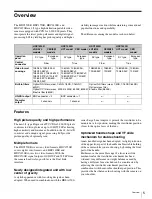
Page 5: ...e and VF slide mechanism for stable shooting A new handle design has been adopted A slight protrusion of the upper front part of the handle enables stable holding of the camera while you are shooting by holding the front part of the handle Furthermore the movable range of a front rear slide mechanism for the viewfinder attachment has been widened Any difference in weight balance caused by having a...

Page 6: ...position Focus assist indicator The focusing level indicator on the viewfinder screen provides a guide for focusing The best focus setting can be easily determined by observing fluctuation of the level indicator as a guide Memory Stick 1 operation The camera is equipped with a Memory Stick port which enables setup data storage and software upgrading using a Memory Stick 1 Memory Stick and are trad...

Page 7: ...ove and below the viewfinder such as a tally lamp battery warning indicator and an indicator to tell you that one or more settings are other than standard This makes it simple to check the status of the camera 4 Zebra pattern A stripe pattern displayed on the viewfinder screen which indicates the portions where the video level is above about 70 or 100 Used to check the video level of the subject O...

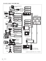
Page 8: ...acket HDVF 20A HDVF 200 HDVF C30WR HDVF C35W Viewfinder HDC1500R 1400R Optical Fiber Cable CAC 6 Return Video Selector Intercom Headset CAC 12 Microphone holder Microphone HDVF EL100 700A Viewfinder HDC1500R 1400R CAC 6 Return Video Selector Intercom Headset Microphone BKP 7911 Script Holder HDVF EL100 HDVF 700A Viewfinder HDC1000R studio camera CAC 6 Return Video Selector Intercom Headset Microph...

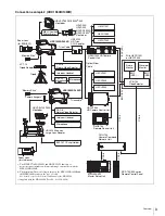
Page 9: ...DVF EL100 700A Viewfinder HDC1550R 1450R CAC 6 Return Video Selector Intercom Headset Microphone BKP 7911 Script Holder HKCU1001 HKCU1003 HKCU1005 HDCU1000 HD Camera Control Unit HKCU1001 HKCU1003 HKCU1005 HDCU1500 HD Camera Control Unit RM B750 Remote Control Unit CNU 700 Camera Command Network Unit MSU 900 950 Master Setup Unit RCP 700 900 series Remote Control Panel BNC SD BNC SD BNC VBS BNC VB...

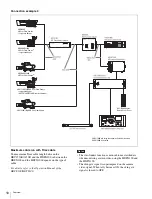
Page 10: ...ng the HDFX100 and the HDTX100 The skin gate signal is superimposed on the camera video signal When tally becomes ON the skin gate signal is forced to OFF HDC1550R 1450R HD Color Video Camera Large Lens Adaptor HDVF C730W C950W Electronic Viewfinder RCP 700 900 series Remote Control Panel HDC1550R 1450R HD Color Video Camera HDC1500R 1400R HD Color Video Camera2 HDC1500R 1400R HD Color Video Camer...

Page 11: ...densation indicator If you find condensation on the body or lens switch the camera off and wait for the condensation to disappear for about one hour Phenomena Specific to CCD Image Sensors The following phenomena that may appear in images are specific to CCD Charge Coupled Device image sensors They do not indicate malfunctions White flecks Although the CCD image sensors are produced with high prec...

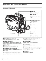
Page 12: ...ever and knob to adjust the viewfinder position towards the front or rear For details on adjusting the viewfinder position see Attaching a Viewfinder on page 21 f Lens cable clamp To secure the cable of the lens not supplied g Lens fixing lever To secure the lens in the lens mount h Lens mount cap The cover can be removed by moving the lens fixing lever upwards Always keep the lens mount covered w...

Page 13: ...nal from the camera control unit is monitored on the viewfinder screen while this button is pressed It function the same as the RET 1 button on the side page 15 and that on the operation panel on the rear of the camera page 17 or 18 You can also assign other functions to this button using the menu displayed on the viewfinder screen c Assignable switch You can assign a function using the menu displ...

Page 14: ...alance adjustment method or the memory used to store the adjusted value when the camera is used in standalone status without connecting a camera control unit PRST preset White balance is adjusted to a preset value corresponding to a color temperature of 3200K A or B Selects memory A or B j DISPLAY switch The functions of the DISPLAY switch are as follows ON Characters and messages showing the came...

Page 15: ...en the camera is used in standalone status without connecting a camera control unit OFF The electronic shutter does not function ON The electronic shutter is activated SEL The shutter speed and shutter mode change each time the switch is set to this position For details see Setting the Electronic Shutter on page 28 e INTERCOM LEVEL control To adjust the intercom earphone volume level The intercom ...

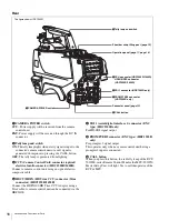
Page 16: ...100 HD Triax CCU Adaptor using a Triax cable A camera control unit can be connected via the HDFX100 d SDI 1 serial digital interface 1 connector BNC type HDC1500R only For HD SDI signal output e PROMPTER2 connector BNC type HDC1500R only For prompter 2 signal output This operates only when a camera control unit having a prompter 2 input is connected f CALL button When you press this button the red...

Page 17: ...the camera page 15 INCOM level control Adjust the intercom audio listening level Line select switch Select the intercom line PROD Producer line ENG Engineer line b RET 1 return video 1 button and select switch The return video signal selected with the switch is displayed on the viewfinder screen while the button is pressed c RET 2 return video 2 button and select switch When other return video sys...

Page 18: ...producer line OFF To turn off the headset microphone for intercom line 2 ENG To talk over the engineer line LEVEL switch REAR The intercom audio listening level is adjusted with the controls on this panel FRONT The intercom audio listening level is adjusted with the INTERCOM LEVEL control on the front of the camera b RET 1 return video 1 button and select switch The return video signal selected wi...

Page 19: ...P and MSU to this connector i GENLOCK IN RET IN PROMPTER external gen lock signal input return video signal input prompter 1 signal output connector BNC type and switch Set the switch according to the signal at the connector GENLOCK IN For input of an external gen lock signal VBS or 3 level sync when the camera is used without a camera control unit connected RET IN For input of the return video si...

Page 20: ...nected to the AUDIO IN CH1 connector LINE When a line level 0 dBu signal source is connected FRONT MIC When using the microphone connected to the MIC 1 IN connector MIC When an external microphone is connected CH2 audio input select switch Set to the appropriate position according to the equipment connected to the AUDIO IN CH2 connector LINE When a line level 0 dBu signal source is connected AES E...

Page 21: ...justing the flange focal length are in different positions on different lenses Refer to the operation manual for the particular lens Adjusting procedure 1 Set the iris control to manual and open the iris fully 2 Place a flange focal length adjustment chart approximately 3 meters from the camera and adjust the lighting to get an appropriate video output level 3 Loosen the Ff flange focal length rin...

Page 22: ...left right positioning ring To adjust the position forward or backward 1 Loosen the viewfinder front rear positioning lever and LOCK knob 2 Slide the viewfinder towards the front or rear of the camera to move it into a good viewing position 3 Tighten the viewfinder front rear positioning lever and LOCK knob Detaching the viewfinder Loosen the viewfinder left right positioning ring pull the viewfin...

Page 23: ...ewfinder shoe of the camera from the front rear positioning mechanism 3 Using the two bolts M4 8 and the washers removed from the camera in step 2 attach the rotation mechanism assembly of the BKW 401 to the camera 4 Adjust the front rear position so that the camera handle does not interfere when you rotate the BKW 401 arm upwards Attaching the Cable Clamp Belt Supplied You can secure the camera c...

Page 24: ...er pad to unlock the shoulder pad 2 Slide the shoulder pad backward or forward until it is in the most convenient position 3 Move the lever down to lock the shoulder pad in the selected position Mounting the Camera to a Tripod Mount the camera to a tripod using a VCT 14 Tripod Adaptor Select an appropriate hole from among those at the bottom of the tripod adaptor considering the balance of the wei...

Page 25: ...d button and pull the lever in the direction of the arrow If the pin of the tripod adaptor does not return to its original position After removing the camera if the pin of the tripod adaptor does not return to its original position hold down the red button and move the lever in the direction of the arrow to return the pin to its original position It is not possible to mount a camera with the pin n...

Page 26: ...era s memory and preserved even when the camera power is turned off Adjusting the black balance Push the AUTO W B BAL switch toward BLK downward Automatic adjustment of black balance begins In automatic adjustment of black balance both the black set and black balance are adjusted During adjustment a message like the one in the figure below will be displayed on the viewfinder screen When the adjust...

Page 27: ...en to satisfy the positional and quantitative requirements illustrated below A white object white cloth a white wall etc near the subject may be used in place of a white pattern Be careful not to have any spots of high illumination in the rectangle 4 Adjust the lens iris opening With a manually adjusted lens Set the opening to an appropriate value With a lens which has automatic iris control Set t...

Page 28: ...ored in the selected memory Each memory can store up to five adjusted values for a total of 10 Setting the Electronic Shutter This section explains the different modes which can be used for the electronic shutter and gives the procedures for setting the shutter mode and shutter speed When a camera control unit or a remote control device such as MSU 900 950 Master Setup Unit and RCP 700 900 series ...

Page 29: ...nob ENTER button to align the arrow marker to TOP and push on the MENU SEL knob ENTER button The TOP MENU screen is displayed 4 Rotate the MENU SEL knob ENTER button to align the arrow marker to OPERATION and push on the MENU SEL knob ENTER button The CONTENTS page of the OPERATION menu is displayed 5 Rotate the MENU SEL knob ENTER buttonto align the arrow marker to VF DETAIL and push on the MENU ...

Page 30: ...be set and push on the MENU SEL knob ENTER button To use the level indicator Setting INDICATOR to ON displays the level indicator on the viewfinder You can set the display format with the menu items below MODE Set the type and position of the indicator LEVEL Set the density and the response speed of the indicator GAIN Set the sensitivity of the indicator 1 OFFSET Set the offset of the focus detect...

Page 31: ...put The menu pages used for the output settings have been registered to the USER menu at the factory POWER SAVE OUTPUT FORMAT TEST OUT SDI 2 OUT HDC1500R SDI OUT HDC1550R 1400R 1450R DOWN CONVERTER Set the following menu items to the settings shown in the table For details on menu operations and the USER menu see Menu Operations on page 34 Outputting the signal being shot camera picture The same t...

Page 32: ...me image as that on the viewfinder screen the output will be obtained in 1080i even if the format setting is 720P To output as HD SDI To output as SD SDI To output as VBS Outputting via Dual Link HDC1500R only The SDI 1 output is assigned to Link A SDI 2 output to Link B This function cannot be used when a camera control unit is connected To output in 1080 59 94P or 1080 50P Menu page Item Setting...

Page 33: ...set to ON f Filter Displays the type of filter currently selected The number 1 2 3 4 or 5 indicates the ND filter and the letter A B C D or E is for the CC filter HDC1500R 1550R only g White balance memory Displays the currently selected white balance automatic adjustment memory W A The WHITE BAL switch is set to A W B The WHITE BAL switch is set to B W P The WHITE BAL switch is set to PRST h Gain...

Page 34: ... settings of the camera The following controls are used to operate the menus Starting Menu Operations To display a menu page Set the DISPLAY switch from OFF to MENU The menu page that last operated will be displayed If it is the first time the CONTENTS page of the OPERATION menu will be displayed To display the TOP MENU screen If you set the DISPLAY switch from OFF to MENU while holding the MENU S...

Page 35: ...is for performing file operations such as writing or clearing the reference file DIAGNOSIS menu This menu enables you to confirm the self diagnostic information To select a menu on the TOP MENU screen 1 Rotate the MENU SEL knob ENTER button to align the arrow marker with the desired menu indication 2 Push on the MENU SEL knob ENTER button The CONTENTS page or the last operated page of the selected...

Page 36: ...tems on the same menu page repeat steps 1 through 4 To specify a character string When you press the MENU SEL knob ENTER button with the arrow marker pointing to an item for which a character string such as a file ID is to be specified a cursor and the list of selectable characters are displayed The displayed cursor can be moved by rotating the MENU SEL knob ENTER button 1 Set the cursor to the po...

Page 37: ...b ENTER button to display the page If a different page is displayed turn the MENU SEL knob ENTER button until the desired page appears then push on the MENU SEL knob ENTER button to select the page Example When you select the USER 2 EDIT page 4 Move the arrow marker to the item to be added this operation is unnecessary if no item exists on the page as shown in the figure for step 3 then push on th...

Page 38: ...e you wish to move the item then push on the MENU SEL knob ENTER button The item selected in step 1 moves to the position that you selected in step 3 In the above example ASSIGNABLE is moved to the top and the other items are moved down one line To insert a blank line Proceed as follows 1 Turn the MENU SEL knob ENTER button to move the arrow marker to the item above which you wish to insert a blan...

Page 39: ... DELETE OK YES NO appears at the upper right 3 To delete turn the MENU SEL knob ENTER button to move the arrow marker to YES then push on the MENU SEL knob ENTER button To move a page Proceed as follows 1 Display the EDIT PAGE screen of the USER MENU CUSTOMIZE menu Turn the MENU SEL knob ENTER button to move the arrow marker to the page that you wish to move The EDIT FUNCTION screen appears 2 Sele...

Page 40: ...Execute by ENTER Execute by pushing on the MENU SEL knob ENTER button OPERATION Menu Notes Page title No Item Default Settings Remarks VF DISPLAY 01 U04 EX ON ON OFF ZOOM OFF ON OFF DISP LEFT LEFT RIGT FOCUS OFF ON OFF Valid only when a serial lens is used ND ON ON OFF CC ON ON OFF Valid with HDC1500R 1550R only 5600K ON ON OFF IRIS ON ON OFF WHITE OFF ON OFF D EXT ON ON OFF GAIN ON ON OFF SHUTT O...

Page 41: ...AN IND ON ON OFF NORMAL AUTO1 AUTO1 AUTO2 MIN MAX EXT IND ON ON OFF FORMAT IND ON ON OFF NORMAL 59 94i or 50i HDC1400R CED E33 and HDC1450R CED models HDC1500R 1550R 59 94i 29 97PsF 50i 25PsF 24PsF 23 98PsF 59 94P 50P HDC1400R JN3 JN4 and HDC1450R UC7 models 59 94i 59 94P HDC1400R CED E33 and HDC1450R CED models 50i 50P VF MARKER 03 U06 MARKER ON ON OFF Except MASK WHITE WHITE BLACK DOT CENTER OFF...

Page 42: ... ON SIZE MIDDLE SMALL MIDDLE LARGE POSITION CENTER LEFT CENTER RIGHT POSITION H 50 0 to 99 POSITION V 50 0 to 99 ZEBRA 06 U08 ZEBRA OFF ON OFF 1 1 2 1 2 ZEBRA1 LEVEL 70 50 to 109 WIDTH 10 0 to 30 ZEBRA2 100 50 to 109 CURSOR 07 U07 CURSOR OFF ON OFF Display only if HDLA attached WHITE WHITE BLACK DOT BOX CROSS BOX BOX CROSS H POSITION 50 0 to 99 Display only if HDLA attached V POSITION 50 0 to 99 W...

Page 43: ...generated This is not a malfunction OFF OFF RETURN1 SW RETURN2 SW ENG PROD VF DETAIL MIX VF 5600K FAN MAX D EXTENDER CED E33 models only When HDLA attached OFF EXTENDER 5600K FAN MAX D EXTENDER Note When you turn D EXTENDER ON or OFF noise may be generated This is not a malfunction RE ROTATION STD STD RVS Specify operation mode of the MENU SEL knob STD Clockwise rotation moves down or increases va...

Page 44: ...NCOM1 INCOM2 D EXTENDER JN3 JN4 SYL UC7 models only RETURN2 SW OFF RETURN1 SW RETURN2 SW ENG PROD D EXTENDER CED E33 models only HANDLE SW1 RETURN1 SW OFF RETURN1 SW RETURN2 SW INCOM1 INCOM2 ZOOM T JN3 JN4 SYL UC7 models only RETURN1 SW OFF RETURN1 SW RETURN2 SW ENG PROD ZOOM T CED E33 models only HANDLE SW2 INCOM1 OFF RETURN1 SW RETURN2 SW INCOM1 INCOM2 ZOOM W JN3 JN4 SYL UC7 models only INCOM1 O...

Page 45: ...ERCOM2 50 MU 1 to 99 RECEIVE SEL1 13 INTERCOM1 RECEIVE SELECT SEPARATE SEPARATE MIX INTERCOM LEFT RIGHT LEFT BOTH JN3 JN4 SYL UC7 models only ENG LEFT RIGHT LEFT BOTH CED E33 models only PROD LEFT RIGHT LEFT BOTH CED E33 models only PGM1 RIGHT RIGHT LEFT BOTH PGM2 RIGHT RIGHT LEFT BOTH TRACKER LEFT RIGHT LEFT BOTH RECEIVE SEL2 14 INTERCOM2 RECEIVE SELECT SEPARATE SEPARATE MIX INTERCOM LEFT RIGHT L...

Page 46: ...or the operator file to be written to a Memory Stick See To specify a character string on page 36 CAM CODE HDC1000 1500 Camera code Display only DATE Display only LENS FILE 18 U12 FILE 1 1 to 17 1 to 16 When using a non serial lens 17 When using a serial lens xxxx Lens file name Changeable only when using a non serial lens F xx F stop number of the lens Changeable only when using a non serial lens...

Page 47: ...ntly set COARSE 0 45 0 35 to 0 90 0 05 steps TABLE STANDARD STANDARD HYPER 5 1 2 3 4 5 6 7 With STANDARD selected 1 equivalent to a camcorder 2 4 5 times gain 3 3 5 times gain 4 equivalent to SMPTE 240M 5 equivalent to ITU R709 6 5 0 times gain 7 5 0 times gain 709 4 1 2 3 4 With HYPER selected 1 325 to 100 2 460 to 100 3 325 to 109 4 460 to 109 GAMMA ON ON OFF TEST OFF OFF SAW 3STEP 10STEP BLACK ...

Page 48: ... master ON ON OFF ABS Highlighted ABS Absolute mode DETAIL 1 P09 DETAIL ON ON OFF LEVEL 0 99 to 99 Absolute value is displayed in ABS mode LIMITER M 0 99 to 99 LIMITER WHT 0 99 to 99 Absolute value is displayed in ABS mode LIMITER BLK 0 99 to 99 Absolute value is displayed in ABS mode CRISP 0 99 to 99 Absolute value is displayed in ABS mode LVL DEP 0 99 to 99 Absolute value is displayed in ABS mod...

Page 49: ...99 G R 0 99 to 99 G B 0 99 to 99 B R 0 99 to 99 B G 0 99 to 99 MATRIX OFF ON OFF PRESET ON ON OFF Invalid when MATRIX is OFF ITU 709 SMPTE 240M ITU 709 SMPTE WIDE NTSC EBU ITU 601 USER OFF ON OFF MULTI OFF ON OFF MULTI MATRIX P13 PHASE 0 0 23 45 68 90 113 135 158 180 203 225 248 270 293 315 338 Select an axis angle at PHASE for which the multimatrix adjustment to be made and set HUE and SAT HUE an...

Page 50: ...23 98PsF 24 00 to 2200 Hz 59 94P 60 02 to 4600 Hz 50P 50 03 to 4600 Hz Note There are some formats that cannot be selected on HDC1400R 1450R NOISE SUP P15 NOISE SUP 0 0 to 100 OFF ON OFF SCENE FILE P16 1 To store and read scene files paint data When storing a file in camera memory specify the number before executing STORE When reading only specify the number 2 3 4 5 STORE Execute by ENTER STANDARD...

Page 51: ...N OFF BLACK SHADING M03 V SAW R G B M 0 0 0 99 to 99 R G and B values can be independently set M master value can also be set for BLACK V PARA 0 0 0 99 to 99 H SAW 0 0 0 99 to 99 H PARA 0 0 0 99 to 99 BLK SET 0 0 0 99 to 99 BLACK 0 0 0 0 99 to 99 MASTER GAIN 0 dB 3 0 3 6 9 12 dB AUTO BLACK SHADING Execute by ENTER 2D BLACK SHAD ON ON OFF OHB MATRIX M04 PHASE 0 0 23 45 68 90 113 135 158 180 203 225...

Page 52: ...AY AUTO ON OFF AUTO AUTO To correspond to the UP TALLY switch setting of HDLA attached CALL TALLY M08 CCU CALL ON ON OFF Valid with CCU connected CAM CALL OFF ON OFF Valid with CCU connected OUTPUT FORMAT HDC1500R M09 U16 CURRENT JN4 SYL models 1080 59 94i V CED E33 models 1080 50i V Displays the current format ACTIVE LINE 1080 1080 720 The selectable frame settings are displayed for the selected ...

Page 53: ...is NTSC HD SYNC OUT V PHASE 0 127 to 127 H PHASE 0 127 to 127 SDI 2 OUT HDC1500R M12 U18 OUTPUT MAIN MAIN VF LINK B RET SD SDI The signal selected for OUTPUT SIGNAL of DOWN CONVERTER is output in SD SDI mode PWR SAVE Displayed in POWER SAVE mode only CHARACTER OFF ON OFF Not displayed if OUTPUT is set to VF or LINK B EMB AUDIO OFF ON OFF 1 MIC1 2 MIC2 3 AES1 4 AES2 Displayed when OUTPUT is MAIN or...

Page 54: ...UTO selected the status is displayed at the right ACTIVE Compensation in progress WAIT Waiting for completion of lens initialization STOP Compensation is turned off for a non applicable lens OTHERS 2 M19 DATE TYPE 5 M D Y 1 Y Mn D 2 Mn D 3 D M Y 4 D M 5 M D Y 6 M D Y Year Mn Month numeric M Month character string D Day FILTER WHT MEM OFF ON OFF Set to ON to use independent white memory at each CC ...

Page 55: ...ator file items in the operator file in internal memory FILE ID max 16 characters Enter a comment for the operator file to be written to a Memory Stick See To specify a character string on page 36 CAM CODE HDC1000 1500 Camera code Display only DATE Display only SCENE FILE F02 1 To store and read scene files paint data When storing a file in camera memory specify the number before executing STORE W...

Page 56: ...ens NAME xxxxx Changeable only when using a non serial lens F NO F1 7 F1 0 to F3 4 Changeable only when using a non serial lens CENTER MARKER To set and store the center marker position H POS Increasing the value moves it to the right V POS Increasing the value moves it downwards H POS 0 20 to 20 V POS 0 20 to 20 STORE Execute by ENTER OHB FILE F05 STORE FILE Execute by ENTER To store the offset v...

Page 57: ...D STATUS D02 OHB OK NG DPR OK NG VDA OK NG DAP OK NG AU OK NG AT OK NG PS OK NG SDI OK NG HDC1500R 1400R only TR OK NG HDC1550R 1450R only PLD VERSION D03 TG Vx xx R IT VDA Vx xx DAP Vx xx AT Vx xx SDI Vx xx TR Vx xx HDC1550R 1450R only DPR Vx xx HKCT Vx xx With HKC T1500 installed only ROM VERSION D04 U22 AT Vx xx PANEL Vx xx With HDLA attached only HKCT Vx xx With HKC T1500 installed only SERIAL...

Page 58: ...writing data You use the Memory Stick in a location subject to the effects of static electricity or electric noise We recommend that you make a backup copy of important data that you record on the Memory Stick Do not attach anything other than the supplied label to the Memory Stick labeling position Attach the label so that it does not stick out beyond the labeling position Carry and store the Mem...

Page 59: ... 56 dB 64 dB NS MAX Horizontal resolution 1000 TV lines at center of screen 5 or higher modulation Geometric distortion Negligible not including lens distortion Optical system specifications Spectral system F1 4 prism Built in filters Color temperature conversion filters A cross filter B 3200K clear C 4300K D 6300K E 8000K ND filters 1 clear 2 1 4 ND 3 1 8 ND 4 1 16 ND 5 1 64 ND Input output conne...

Page 60: ... CAMERA de l unité de commande de caméra LEMO FUW 3K 93C TLMC96 au connecteur CCU de la caméra Attention concernant le câble optique électrique composite Pour la connexion entre l unité de commande de caméra et une caméra utilisez un câble optique électrique composite avec connecteurs spécifiés dans ce manuel pour assurer la conformité avec la réglementation EMC Für Kunden in USA Kanada Europa Aus...

Page 61: ...o comply with the limit for EMC regulations Pour les utilisateurs aux Etats Unis au Canada en Europe à l Australie et à la Nouvelle Zélande Connecteurs pour les câbles optiques électriques composites LEMO PUW 3K 93C TLCC96 au connecteur CAMERA de l unité de commande de caméra LEMO FUW 3K 93C TLMC96 au connecteur CCU de la caméra Attention concernant le câble optique électrique composite Pour la co...

Page 62: ...NC type 1 TEST OUT BNC type 1 GENLOCK IN RET IN PROMPTER BNC type 1 1 Vp p 75 ohms RET CTRL 6 pin 1 REMOTE 8 pin 1 TRACKER 10 pin 1 CRANE 12 pin 1 Supplied accessories Operation manual 1 Cable clamp belt 1 set Switch label 1 2 1 each Design and specifications are subject to change without notice HDC1450R General Power requirements 180 V DC 1 0 A max 12 V DC 7 A max Operating temperature 20 C to 45...

Page 63: ...onochrome HDVF 550 5 type monochrome HDVF C30WR 2 7 type color HDVF C35W 3 5 type color HDVF C730W 6 3 type color HDVF C950W 9 type color HDLA1500 1505 Large Lens Adaptor HDLA1507 Large Viewfinder Adaptor CAC 12 Microphone Holder CAC 6 Return Video Selector BKW 401 Viewfinder Rotation Bracket HKC DF14 Dual Optical Filter Unit VCT 14 Tripod Adaptor Memory Stick Low repulsion Shoulder Pad A 8286 346...

Page 64: ...64 Specifications Dimensions HDC1500R 1400R HDC1550R 1450R Unit mm inches 105 4 1 4 268 10 5 8 198 7 7 8 362 14 3 8 135 5 3 8 Unit mm inches 105 4 1 4 268 10 5 8 198 7 7 8 362 14 3 8 156 6 1 4 ...

Page 65: ... for use by the purchasers of the equipment described in this manual Sony Corporation expressly prohibits the duplication of any portion of this manual or the use thereof for any purpose other than the operation or maintenance of the equipment described in this manual without the express written permission of Sony Corporation ...

Page 66: ...Sony Corporation HDC1500R JN4 SYL CED E33 HDC1400R JN3 JN4 CED E33 HDC1550R UC7 CED HDC1450R UC7 CED 4 140 776 01 2 Printed in Japan 2009 02 13 2009 ...

Reviews: