1-14 (E)
SRW-5800
8
1
External view
External view
1
5
9
6
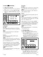
1-9. Switch Settings on Connector Panel
When the unit is installed, be sure to perform the following
setup.
Refer to the operation manual “Section 2 Location and
Function of Parts” for setup.
.
75
Z
termination switch of reference video input
VIDEO CONTROL: 9-pin (female)
Pin No.
Signal
1
GND
2
RM TX (
_
)
3
RM RX (
+
)
4
GND
5
——
6
GND
7
RM TX (
+
)
8
RM RX (
_
)
9
GND
NETWORK 1: RJ-45 modular jack
Standard : Complied with IEEE 802.3u (100BASE-TX)
and IEEE 802.3 (10BASE-T)
Pin No.
I/O
Signal
1
O
TXD (
+
)
2
O
TXD (
_
)
3
I
RXD (
+
)
4
—
NC
5
—
NC
6
I
RXD (
_
)
7
—
NC
8
—
NC


