background image

1-30 (E)

SRW-5800

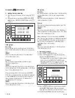
3. Memory Stick format

m
.

No Memory Stick can be used unless it is formatted by
the unit.
Format a Memory Stick to be used before storing the
system settings.

.

When a Memory Stick is formatted, its data is cleared
completely.

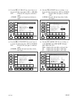
(1) Press the 

[F1]

 (FORMAT CARD) key with the

SYSTEM CARD BANK menu.
A confirmation message appears.

To cancel formatting

Press the 

[CLR]

 (CLEAR) key while the confirmation

message is displayed.

(2) Press the 

[F1]

 (FORMAT CARD) key while pressing

the 

[SFT]

 (SHIFT) key.

Formatting the Memory Stick starts and a directory is
created.

4. Loading the settings from the system bank to

a Memory Stick

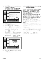
(1) Insert a Memory Stick into the slot of the unit, and

display the SYSTEM CARD BANK menu.

(2) Press the 

[F8]

 (DIRECTION) key with the SYSTEM

CARD BANK menu, and choose   direction.
The left cursor bar blinks.

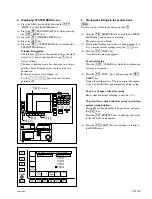
(3) Press the 

[*]

 key to move   to the right (unit data

side), and position the lighting cursor bar at the item to
be stored in a Memory Stick using the 

[(]

/

[)]

 keys.

To store current system settings in a Memory Stick

Position the lighting cursor bar at the item 

[C]

.

To store eight pieces of system bank data collective-
ly in a Memory Stick

Press the 

[F7]

 (SELECT ALL) key.

n

If any protected bank number exists in the system
bank, the 

[F7]

 (SELECT ALL) key cannot be select-

ed.

(4) Press the 

[&]

 key to move   to the left (Memory Stick

side), and position the blinking cursor bar at the bank
number of the save destination (system bank of
Memory Stick) using the 

[(]

/

[)]

 keys.

(5) Press the 

[F9]

 (COPY) key.

A confirmation message appears.

To cancel storing

Press the 

[CLR]

 (CLEAR) key while the confirmation

message is displayed.

(6) Press the 

[F9]

 (COPY) key while pressing the 

[SFT]

(SHIFT) key.
Storing the settings starts. The title of the save origin
appears at the save destination (Memory Stick side)
upon completion of the storing.

To give or change a title after saving

Edit system bank titles referring to Section 1-11-7.

To protect the system bank after saving (protection
against wrong deletion)

Position   at a bank number to be protected, and press
the 

[ALT]

 key.

Press the 

[F2]

 (PROTECT) key to light up a key mark

to the left of the bank number.

(7) Press the 

[F10]

 (EXIT) key several times to return to

the HOME menu.

5. Loading the settings from Memory Stick to the

system bank

n

When updating the current system settings to those stored
in a Memory Stick, eject the tape and confirm that the
standby mode is set to off before reading  the data.

(1) Insert the Memory Stick storing the data to be loaded

into the slot, and display the SYSTEM CARD BANK
menu.

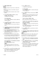
(2) Press the 

[F8]

 (DIRECTION) key with the SYSTEM

CARD BANK menu, and choose   direction.
The right cursor bar blinks.

(3) Press the 

[&]

 key to move   to the left (Memory Stick

side), and position the lighting cursor bar at the bank
number of the save origin (system bank of Memory
Stick) using the 

[(]

/

[)]

 keys.

Summary of Contents for HDCAM-SR SRW5800

Page 1: ...INSTALLATION MANUAL 1st Edition Serial No 10001 and Higher HD DIGITAL VIDEOCASSETTE RECORDER SRW 5800 ...

Page 2: ...n against overloading of branch circuit When this product is installed in a rack and is supplied power from an outlet on the rack please make sure that the rack does not overload the supply circuit 2 Providing protective earth When this product is installed in a rack and is supplied power from an outlet on the rack please confirm that the outlet is provided with a suitable protective earth connect...

Page 3: ... 1 11 1 Setting the System 1 17 E 1 11 2 Compatibility of REC and PB 1 20 E 1 11 3 Meta Data Setting 1 21 E 1 11 4 Input Output Phase Settings 1 24 E 1 11 5 Storing and Reading System Settings in from System Bank 1 26 E 1 11 6 Storing Reading System Settings in from Memory Stick 1 28 E 1 11 7 Editing Titles of the System Bank 1 31 E 1 11 8 Checking Saved System Bank Data in Detail 1 32 E 1 11 9 Co...

Page 4: ...uts Volume 3 Schematic Diagrams These manuals describe the maintenace and service information service over view adjustments board layouts schematic diagrams detailed parts list etc for this unit Protocol Manual of Remote 9 pin Connector Available on request This manual explains the protocol for controlling the VTR via the RS 422A 9 pin serial remote Interface Manual of Parallel I O 50 pin Connecto...

Page 5: ... the front and rear of the unit more than 30d c Fix the unit securely to avoid drop when the unit is operat ed at not horizontal place 1 1 Installation Procedure Installation procedure of this unit is shown on the follow ing flowchart Refer to each section about detail of each flow The operation manual is also required to do marked flow 1 3 Operating Conditions 1 4 Power Supply 1 5 Installation Sp...

Page 6: ...Sony Sales Office Service Center w Use the approved Power Cord 3 core mains lead Appliance Connector Plug with earthing contacts that conforms to the safety regulations of each country if applicable Use the Power Cord 3 core mains lead Appliance Connector Plug conforming to the proper ratings Volt age Ampere If you have questions on the use of the above Power Cord Appliance Connector Plug please c...

Page 7: ...le when operating the unit for inspection with the upper lid re moved If it takes a long time blow to the unit by an electric fan to cool the unit 1 5 Installation Space When installing the installation space must be secured in consideration of the ventilation and service operation Do not block the ventilation slots at the left side and right side panels and vents of the fans Leave a space around ...

Page 8: ... notes mentioned below w To prevent toppling over the rack fix it on the horizontal and firm floor securely with bolts etc When installing the unit in an Outside Broadcasting van be sure to fix the unit to the rack using the screws and ornamental washers supplied with the rack mount kit c Use the specified rack mount rail The use of other rail of low strength may drop the unit and cause the risk o...

Page 9: ...rail out of the intermediate rails while pressing each stopper 6 Remove the ten screws from both sides left and right of the unit as shown in the figure below 7 Attach the two inner rails to both sides left and right of unit with the removed screws in the step 6 Tightening torque 120 x 10 _2 N m 12 2 kgf cm m Be sure to use the B4 x 6 screws when attaching the inner rail The use other sized screws...

Page 10: ...iner in the direction of the arrow and then loosely attach the front rail bracket to the outer rail with a plate nut large and the two screws Attaching the rack angles handles 8 Remove the four screws from both sides left and right of the unit n Keep these screws B4 x 6 Be sure to use these screws when directly fixing the side panels without the rack angles The use of longer screws such as the scr...

Page 11: ...ers and four plate nuts small Rail bracket fixing screws B4 x 8 Rack 50 to 55 mm Outer rail Rack angle Rail bracket 13 Check that the two intermediate rails attached to the rack are parallel 14 As shown in the following figure adjust each front side position of the outer rails on both sides left and right so that the distance from the surface of the rack to the tip of the rail becomes within the r...

Page 12: ...pths of the rack The unit is fixed to the rack by the lock mechanism Attempt to pull the rack angles and confirm that the unit cannot be pulled out of the rack 23 Secure the unit to the rack with the four screws RK5 x 14 and four ornamental washers Tightening torque 120 x 10_2 N m 12 2 kgf cm Mounting in rack c Be sure to carry the unit by the two persons or more 17 Set each ball retainer to the p...

Page 13: ... D SUB 9P MALE and 1 560 651 00 JUNCTION SHEEL 9P 1 561 749 00 VIDEO CONTROL 9P D SUB 9P MALE and 1 561 651 00 JUNCTION SHELL 9P 1 561 749 00 HD SDI INPUT BNC 75Z MALE 2 1 569 370 12 HD SDI OUTPUT FORMAT CONV OUT OPTION FC OUT B OPTION SD SDI OUTPUT BNC 75Z MALE 3 1 569 370 12 PHONES JM 60 stereo phone plug _ Upper control panel NETWORK 1 Separately available 1 Coaxial cable length max 600 meters ...

Page 14: ...d CH11 12 AES EBU digital audio Complies with SMPTE 299M SMPTE 276 AES 3id 1995 5 HD SDI INPUT A BNC x 2 outputs the input monitor x 2 HD SDI INPUT B OPTION Serial digital interface 1 485 Gbit s complies with SMPTE 292M SMPTE 372M Option HKSR 5803SQ HQ Remote connectors 4 REMOTE 2 PARALLEL I O 50P D SUB 50P connector 4 REMOTE1 IN 9P D SUB 9P connector RS 422A interface Remote control 4 REMOTE1 I O...

Page 15: ...ES EBU digital audio Complies with SMPTE 299M SMPTE 276M AES 3id 1995 5 HD SDI OUTPUT A BNC x 6 including 1 for character superimpose HD SDI OUTPUT B OPTION Serial digital interface 1 485 Gbit s complies with SMPTE 292M SMPTE 372M Option HKSR 5803SQ HQ 5 SD SDI OUTPUT BNC x 3 including 1 for character superimpose Serial digital interface 270 Mbit s complies with SMPTE 259M ITU R BT 656 5 FORMAT CO...

Page 16: ...SETTE OUT IN STATUS 13 OUT O TAPE HDCAM SR TAPE STATUS 14 OUT X SPARE SPARE 15 OUT X SPARE SPARE 16 12V Maximum output current 50 mA 17 GND SIGNAL GND 18 IN O PREROLL CLOSURE SW PREROLL 19 IN O STBY ON CLOSURE SW STANDBY ON 20 IN O REW CLOSURE SW REW 21 IN O ENTRY IN CLOSURE SW ENTRY IN 22 IN O STBY OFF CLOSURE SW STANDBY OFF 23 IN O EJECT CLOSURE SW EJECT 24 OUT X REC REC STATUS 25 OUT X CH CONDI...

Page 17: ...N STATUS 47 OUT X PLAY PLAY STATUS 48 OUT X REMOTE REMOTE STATUS 49 OUT X ALARM SYSTEM ALARM STATUS 50 OUT O PREROLL PREROLL STATUS 1 Input 47 kZ pull up to 5 V close open Output 10 kZ pull up to 5 V 0 V or open 2 The pins described as O mark are possible to change the setting Refer to the optional interface manual for changing the setting RS232C 9 pin male REMOTE 1 IN 9 pin female REMOTE 1 I O 9 ...

Page 18: ...n manual Section 2 Location and Function of Parts for setup 75 Z termination switch of reference video input VIDEO CONTROL 9 pin female Pin No Signal 1 GND 2 RM TX _ 3 RM RX 4 GND 5 6 GND 7 RM TX 8 RM RX _ 9 GND NETWORK 1 RJ 45 modular jack Standard Complied with IEEE 802 3u 100BASE TX and IEEE 802 3 10BASE T Pin No I O Signal 1 O TXD 2 O TXD _ 3 I RXD 4 NC 5 NC 6 I RXD _ 7 NC 8 NC ...

Page 19: ... 81 Board m Refer to Section 1 15 for removing and reattaching the plug in boards The switches S1200 and S2200 are Factory use Never change the setting The switches S2201 and S2202 are used for the audio monitor output adjustment Never change the setting since the adjustment is completed at factory Top View APR 81 Board Side A ...

Page 20: ...ng the switches on the CUE 13 board CUE output level n The switch S100 is Factory use Never change the setting CUE output level settings Ref No Switches state Knob position S101 4 dBm 600 Z 0 dBm 600 Z _3 dBm 600 Z _20 dBm 600 Z Factory setting Top View CUE 13 Board Side A 1 2 O N 3 4 1 2 O N 3 4 1 2 O N 3 4 1 2 O N 3 4 ...

Page 21: ...e F1 SYSTEM MODE key several times for setting to the 1080 x 1920 or 720 x 1280 F1 F2 F3 F4 DIAG ALT SYSTEM SCAN SYSTEM MENU 1080x1920 59i 422 YPbPr F1 SYSTEM MODE 1080x1920 F2 SYSTEM SCAN MODE Interlace F3 SYSTEM FRAME 29 97Hz F4 SYSTEM SIGNAL MODE 422 YPbPr F6 FRAME CONVERT 444 1080 59 94i F7 ACTIVE LINE HDCAM OFF F8 CANCEL F9 Exec of Reset VTR Sys STOP STANDBY OFF EJECT SYSTEM MODE SYSTEM SCAN ...

Page 22: ...EM FRAME 29 97Hz F4 SYSTEM SIGNAL MODE 422 YPbPr F6 FRAME CONVERT 444 1080 29 97P F7 ACTIVE LINE HDCAM OFF F8 CANCEL F9 Exec of Reset VTR Sys STOP STANDBY OFF EJECT F5 F6 F7 F8 F9 F10 SYSTEM MENU 444 1080 29 97PsF 422 720 59 94p F1 F2 F3 F4 DIAG ALT F5 F6 F7 F8 F9 F10 SYSTEM SCAN SYSTEM MODE SYSTEM SCAN SYSTEM FRAME SYSTEM SIGNAL FRAME CNVERT ACTIVE LINE CANCEL EXEC EXIT 1080x1920 29PsF 422 YPbPr ...

Page 23: ...AN MODE Interlace F3 SYSTEM FRAME 29 97Hz F4 SYSTEM SIGNAL MODE 422 YPbPr F6 FRAME CONVERT 444 1080 59 94i F7 ACTIVE LINE HDCAM OFF F8 CANCEL F9 Exec of Reset VTR Sys STOP STANDBY OFF EJECT Are You Sure If you press F9 again then EXECUTE Or press F8 to CANCEL F1 F2 F3 F4 DIAG ALT SYSTEM SCAN SYSTEM MODE SYSTEM SCAN SYSTEM SIGNAL FRAME CNVERT ACTIVE LINE CANCEL EXEC EXIT SYSTEM FRAME 1080x1920 29Ps...

Page 24: ...STEM FRAME FREQ Hz 23 98 24 25 29 97 30 25 29 97 30 50 1 59 94 1 25 29 97 30 23 98 24 25 29 97 30 23 98 PsF Interlace PsF Interlace Progressive 24 25 29 97 30 25 29 97 30 Video audio time code Normal playback Video audio time code 0 1 off speed playback Video audio Off speed playback Time code Convertible depending on menu setting HDCAM Video Off speed playback Audio Mute Time code Convertible dep...

Page 25: ... selection menu appears F2 F3 F4 DIAG F5 F6 F7 F8 F9 F10 SFT ALT F1 1 SFT DIAG 5 F1 3 F9 4 ALT 2 SFT F8 2 Format selection 1 Press the F2 HDCAM SR key or F4 DOWN CONV key according to your system F2 HDCAM SR The meta data line setting menu appears Perform 3 Setting the meta data line F4 DOWN CONV The meta data line setting menu of down convert output appears Perform 5 Setting the meta data line of...

Page 26: ... DATA SETUP menu When the changed data is not to be saved select NO OPERATION and press the F10 EXIT key 3 Press the F10 EXIT key several times to return to the OTHERS CHECK menu When setting input output phases continuously proceed to Section 1 11 4 4 Turn OFF the POWER switch and turn ON again In selecting F2 F2 F2 F2 F2 HDCAM SR 3 Setting the meta data line 1 Move the cursor to the item to be s...

Page 27: ...enu returns to the DC OUTPUT META DATA LINE SELECT menu When the changed data is not to be saved select NO OPERATION and press the F10 EXIT key 3 Press the F10 EXIT key several times to return to the OTHERS CHECK menu When setting input output phases continuously proceed to Section 1 11 4 4 Turn OFF the POWER switch and turn ON again In selecting F4 F4 F4 F4 F4 DOWN CONV 5 Setting the meta data li...

Page 28: ...T AES MO OUT F1 DIAG F1 F2 F4 ALT F5 F6 F7 F8 F9 F10 AUDIO INPUT LTC OUT EXIT OTHERS CHECK PHASE SETTING HD SDI OUTPUT ADV 90H SD SDI OUTPUT ADV 2H AUDIO PB OUTPUT ADV 1FRAME AUDIO INPUT DELAY 1FRAME TC INPUT DELAY 1FRAME AES EBU MONITOR OUTPUT LINE LTC OUTPUT LINE AU PB OUT NVRAM CTL HD SDI OUT SD SDI OUT TC INPUT AES MO OUT F3 F3 F4 DIAG F5 F6 F7 F8 F9 F10 SFT ALT F1 F2 1 SFT DIAG 5 F2 3 F9 4 AL...

Page 29: ...T LINE LTC OUTPUT LINE AU PB OUT NVRAM CTL HD SDI OUT SD SDI OUT TC INPUT AES MO OUT F5 DIAG F1 F2 F3 F4 ALT F5 F6 F8 F9 F10 AUDIO INPUT LTC OUT EXIT OTHERS CHECK PHASE SETTING HD SDI OUTPUT ADV 90H SD SDI OUTPUT ADV 2H AUDIO PB OUTPUT ADV 1FRAME AUDIO INPUT DELAY 1FRAME TC INPUT DELAY 1FRAME AES EBU MONITOR OUTPUT LINE LTC OUTPUT LINE AU PB OUT NVRAM CTL HD SDI OUT SD SDI OUT TC INPUT AES MO OUT ...

Page 30: ...T AES MO OUT F8 DIAG F1 F2 F3 F4 ALT F5 F6 F7 F8 F9 F10 EXIT NVRAM CONTROL NO OPERATION SAVE ALL DATA ALL DATA PREVIOUS RESET ALL DATA OTHERS CHECK 1 11 5 Storing and Reading System Settings in from System Bank Up to eight current system settings made by the SYSTEM menu META DATA SETUP menu and PHASE SET menu can be saved in the system bank of the unit with respective titles The settings can also ...

Page 31: ...T key Press the F2 PROTECT key to light up a key mark to the left of the bank number 5 Press the F10 EXIT key several times to return to the HOME menu 2 Displaying SYSTEM BANK menu 1 Press the DIAG button while pressing the SFT SHIFT key with the HOME menu 2 Press the F8 MAINTE EXEC key while pressing the SFT SHIFT key 3 Press the F9 OTHERS CHECK key 4 Press the ALT key 5 Press the F5 SYSTEM BANK ...

Page 32: ...mber appears at the left item C n If the system settings are updated after reading the title displayed at C remains unchanged 5 Press the F10 EXIT key several times to return to the HOME menu 1 11 6 Storing Reading System Settings in from Memory Stick The system settings saved in the system bank of the unit can be stored in a Memory Stick with a title The system settings saved in a Memory Stick ca...

Page 33: ...item shows Memory Stick data and 1 to 8 show system bank data of the Memory Stick The item of the lighting cursor bar shows the save origin and the item of the blinking cursor bar shows the save destination shows an item for title editing etc Use the keys to choose the item pointed by F2 F3 F4 DIAG F5 F6 F7 F8 F9 F10 SFT ALT F1 1 SFT DIAG 3 F9 5 F6 2 SFT F8 4 ALT DIAG F1 F2 F3 ALT F5 F6 F7 F8 F9 F...

Page 34: ... the left Memory Stick side and position the blinking cursor bar at the bank number of the save destination system bank of Memory Stick using the keys 5 Press the F9 COPY key A confirmation message appears To cancel storing Press the CLR CLEAR key while the confirmation message is displayed 6 Press the F9 COPY key while pressing the SFT SHIFT key Storing the settings starts The title of the save o...

Page 35: ...the F7 SELECT ALL key cannot be select ed 4 Press the key to move to the right unit data side and position the blinking cursor bar at the bank number of the save origin unit system bank using the keys To update the current system settings Position the blinking cursor bar at the item C 5 Press the F9 COPY key A confirmation message appears To cancel reading Press the CLR CLEAR key while the confirm...

Page 36: ...ing item with red characters cannot be loaded to the current system settings but can be copied between Memory Stick and system bank of the unit 4 Press the F4 DATA DETAIL key continuously to display further detailed data and to return to the SYSTEM BANK menu or SYSTEM CARD BANK menu 1 11 9 Compatibility of System Bank Data The data saved in a Memory Stick on the unit is also available for other SR...

Page 37: ...l 1 After pressing the unlock buttons open the lower control panel in the arrow direction n The inclination of the lower control panel can be adjusted to five steps about 18d each time between vertical and horizontal Close the Lower Control Panel 1 While lifting the outer stays by the forefinger close the lower control panel as shown in the figure ...

Page 38: ... ITEM 102 When the setup menu ITEM 005 is set to input The STOP button blinks when the signal is not input to the HD SDI INPUT A connector or when a different signal from the selected system is input When the setup menu ITEM 005 is set to external The STOP button blinks when no reference signal is input to REF INPUT 1 connector or when the different reference video signal REF INPUT 1 from the syst...

Page 39: ...the TIME CODE use the TC menu in the function menu Set the TIME CODE as follows when the editor or the VTR with edit function is connected Button Item Setting F6 REGENE SOURCE int L F7 TCG MODE preset F8 RUN MODE free 1 14 2 Settings for Setup Menu Set the setup menu ITEM 304 VAR SPEED RANGE FOR SYNCHRONIZATION to wide 1 14 3 VTR Constant Values Settings of Editor Set the VTR constant values accor...

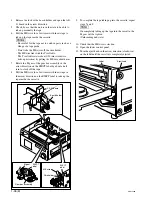
Page 40: ...s replaced refer to the mainte nance manual volume 1 Removing 1 Fully loosen the fixing screw 2 Slide the knobs on upper lid front assembly each in the inside Move the knobs to the outside to fix the upper lid front assembly 3 Remove the upper lid front assembly in the arrow direction 4 Fully loosen the two fixing screws 5 Remove the upper lid rear assembly by moving in the direction indicated by ...

Page 41: ... Tightening torque 120 x 10_2 N m 12 2 kgf cm 1 16 Taking Out the Cassette in Tape Slacking When slacking the tape in this unit follow the steps below to take out the cassette tape m Turn off the power and unplug the power cord before taking out the cassette tape Being careful not to damage the tape take out the cassette tape with care 1 Fully loosen the fixing screw 2 Slide the knobs on upper lid...

Page 42: ... board in the arrow direction 5 Check by eye that the unit is in the state to be able to take up manually the tape 6 Pull the ME wire for a few times with short steps to take up the tape inside the cassette m Be careful for the tape not to catch in parts such as a flange of a tape guide Don t take the ME wire off the wire holder The ME wire links with the T real table The T real table rotates abou...

Page 43: ...combination of each system making the sheets are conve nient Make use of the check sheets in prevention of setting error Model name Serial No _____________________________ Firmware SYS1 ROM version ____________________________ SYS2 ROM version ____________________________ SY ROM version ____________________________ CP ROM version ____________________________ RS 232C baud rate bps Hours meter Write...

Page 44: ...g REMOTE OFF LOCAL Switches on the board n Never change the setting of Factory use switches Board Name Channel Switch No Factory setting Setting knob position AE 31 HEAD TUNE switch CH1 S100 Factory use CH2 S200 Factory use APR 81 Monitor output level L S2201 Factory use 1 output headroom R S2202 Factory use 1 CUE 13 CUE audio output level S101 4 dBm 600 Z dBm 600 Z 1 Setting at shipping vary with...

Page 45: ...setting knob position APR 81 S1200 S2200 CP 393 S1 S2 S300 CUE 13 S100 DVP 43 S200 HKSR 5802 S800 S1301 EQ 102 S400 S403 S601 S2200 S2901 S3300 S3301 S4000 Continued 1 2 O N 3 4 1 2 O N 3 4 5 6 7 8 1 2 O N 3 4 1 2 O N 3 4 5 6 7 8 1 2 O N 3 4 1 2 O N 3 4 5 6 7 8 1 2 O N 3 4 5 6 7 8 1 2 O N 3 4 5 6 7 8 1 2 O N 3 4 5 6 7 8 1 2 O N 3 4 5 6 7 8 1 2 O N 3 4 1 2 O N 3 4 0 1 2 O N 3 4 1 2 O N 3 4 1 2 O N ...

Page 46: ......

Page 47: ... de Sony Corporation Sony Corporation interdit formellement la copie de quelque partie que ce soit de ce manuel ou son emploi pour tout autre but que des opérations ou entretiens de l équipement à moins d une permission écrite de Sony Corporation Das in dieser Anleitung enthaltene Material besteht aus Informationen die Eigentum der Sony Corporation sind Die Sony Corporation untersagt ausdrücklich ...

Page 48: ...Printed in Japan Sony Corporation 2007 10 08 2007 SRW 5800 SY J E 3 286 476 01 ...

Reviews: