39
Appendices
Additional Functions of an MSU-1000/
1500 in 3D Operations
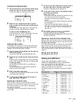
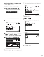
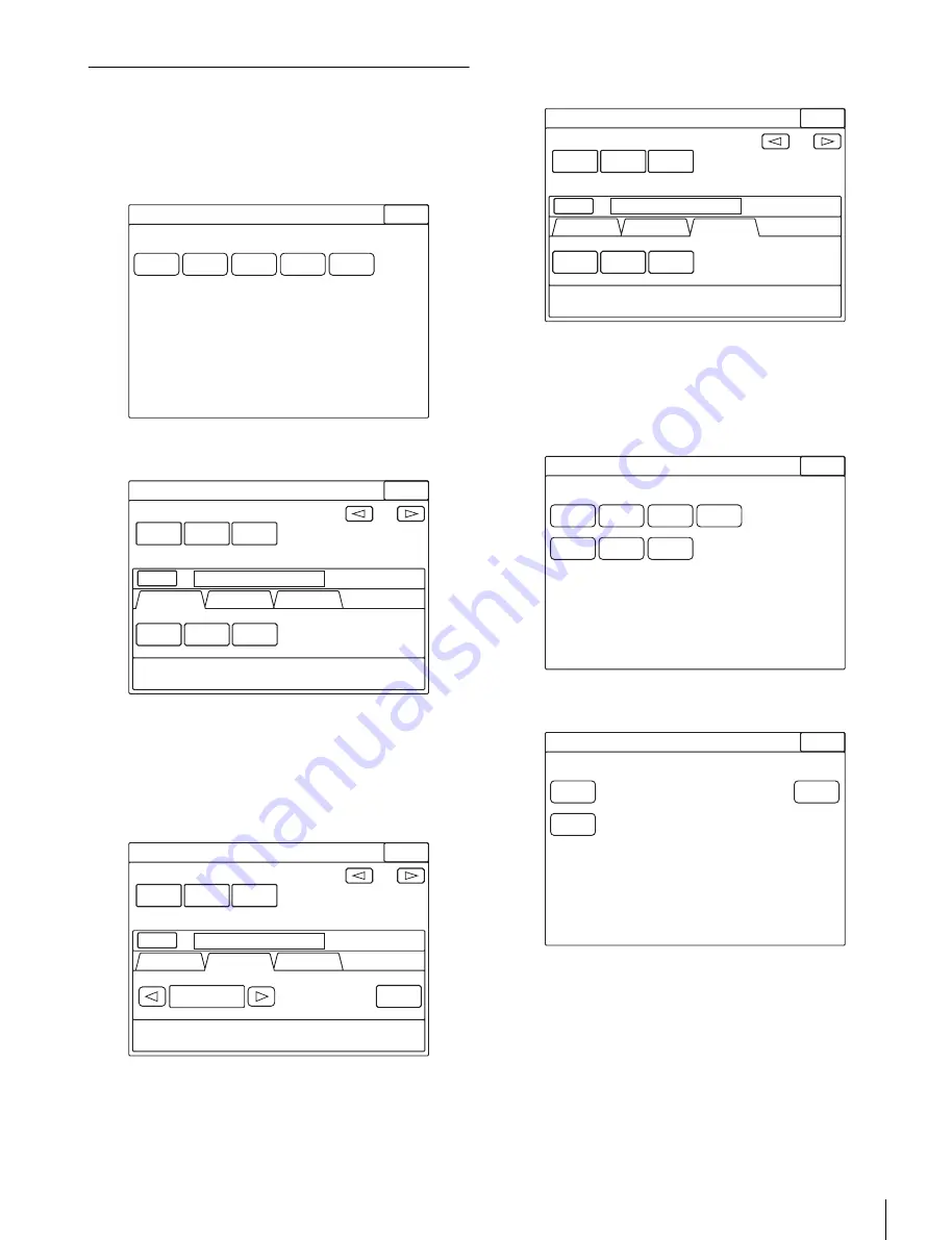
Operations of CCU 3D Monitor functions
1
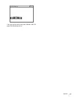
Select CCU on the Maintenance menu screen.
2
Select 3D Monitor.
3
Select a signal to be output from the Monitor Output
connector of a CCU on the Select tab.
For a CCU with an HKCU2005 3G Signal Link Interface
Unit mounted, 3D Monitor can be selected.
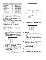
4
Select a function to be used on the Mode tab.
5
Move the border line by pressing the Border Line if the
Split or Mirror function is selected.
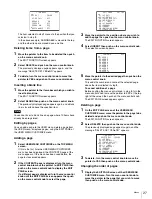
6
Select a camera to be controlled in 3D mode with the
buttons of 3D Camera Control on the CAM Ctrl tab.
The same selection can be made on the 3D CAM Control page
of the Configuration menu.
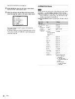
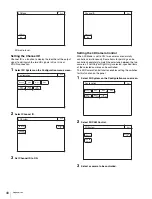
Setting the 3D Mode
1
Select 3D System on the Configuration menu screen.
2
Select 3D Mode.
3
Set 3D Mode to ON.
Exit
Maintenance
Camera
Lens
CCU
SD
Adjustings
VCS
3D Monitor
1/1
Phase
Clear
Select
Mode
CAM Ctrl
Monitor
Output
3D
Monitor
Exit
Left
3D Monitor
Right
14
Position
CCU
3D Monitor
1/1
Phase
Clear
Select
Mode
CAM Ctrl
Monitor
Output
3D
Monitor
Exit
14
Position
CCU
Side by Side
Border
Line
3D Monitor Mode
3D Monitor
1/1
Phase
Clear
Select
Mode
CAM Ctrl
Monitor
Output
3D
Monitor
Exit
Left Only
Both
Right Only
14
Position
CCU
3D Camera Control
Exit
Configuration
Camera
CCU
MSU
CNU
RCP
Assignment
Multi
Format
3D
System
Exit
3D System
3D Mode
Channel
ID
3D CAM
Control

