background image

5

Compatible Devices / Overview

Compatible Devices

This unit can be connected to the following devices (as of 
August 2010). When connecting, be sure to update the PLD 
and software to the latest version.
For details on updating, consult your Sony representative.

a) An HKCU-HB10 3G Fiber Transmission Unit must be installed.
b) An HKCU-HB15 3G Fiber Transmission Unit must be installed.
c) Not used in 3D operation.

About this manual

This manual provides the information required for using this 
unit with the devices mentioned above. If another device is to 
be connected, refer to the operation manual supplied with the 
device to be connected. 

Overview

The HDFA-200 is an intelligent transmission interface unit with 
high bit-rate transmission technology. The unit enables 3D 
multicamera system operation if you connect two cameras (left 
and right, hereafter referred to as L/R) such as HDC-P1 HD 
Multi Purpose Cameras to a Camera Control Unit via this unit, 
using a single optical fiber cable. This also enables 
transmission of RGB 4:4:4 signals if you connect an F35 
Digital Cinematography Camera and creates a multicamera 
system with 35-mm imagers.

Features

Improving operation efficiency by connecting a 
single fiber cable

High bit-rate digital optical transmission technology enables 
you to send signals from two cameras to a CCU, using a single 
optical fiber cable, and also to supply power and genlock 
signals to the two cameras. 

Power of up to 13 A (maximum 14 V) can be supplied from this 
unit in total, but available power is limited depending on the 
devices to be connected or the length of an optical fiber cable. 
For details, see “Notes on Power Supplied from This Unit” 
(page 14).

3D multicamera operation

The unit is equipped with 2-channel audio input, intercom, and 
trunk data (general-purpose control signal via a CCU and 
HDFA-200) transmission functions that enable system 
operation of a 3D multicamera system equivalent to that of an 
existing 2D camera system.

Improving operation with a single remote control 
panel

The L/R cameras can simultaneously be controlled with a 
remote control panel connected to a CCU. It is also possible to 
perform offset control of the left and right cameras, which 
allows 3D system camera operation with high flexibility.

3D monitoring with a viewfinder

On the screen of a viewfinder connected to the VF connector 
on this unit, picture from the left or a right camera only, or 
pictures from both the L/R cameras can be monitored. For L/R 
camera pictures, split, mix, or Y-difference display function 
required for rig adjustment for camera setup can be switched.

Linking with an MPE-200 with lens meta data 

If a lens supporting serial data transmission is used, the focal 
length of the lens, zoom position, and iris data are overlaid on 
an HD-SDI signal output from the CCU as meta data, which 
supports linking operation with an MPE-200 Multi Image 
Processor.

Remote operation of a 3D rig

1)

 using a trunk data 

line

General-purpose control signals of up to 150 kbaud can be 
transmitted as trunk data. The RS-232C or RS-422 signals 

Product type

Model name

3D multicamera

HDC-P1

HDC1600R/1500R/
1400R/1550R/
1450R

HDC1600/1500/
1550

Camera control unit

HDCU1000

a)

/1500

b)

RGB 4:4:4 transmission (2D) 
camera

F35

Master Setup Unit

MSU-1000/1500

Remote Control Panel

RCP-1000

c)

/1001

c)

/

1500/1501/1530

Summary of Contents for HDFA-200

Page 1: ...OPERATION MANUAL English 1st Edition Revised 1 HD OPTICAL FIBER ADAPTOR UNIT HDFA 200 ...

Page 2: ...ul interference in which case the user will be required to correct the interference at his own expense You are cautioned that any changes or modifications not expressly approved in this manual could void your authority to operate this equipment All interface cables used to connect peripherals must be shielded in order to comply with the limits for a digital device pursuant to Subpart B of Part 15 ...

Page 3: ...er Diode Properties Wave length 1310 40 nm Emission duration Pulse Modulation Laser output power 141 μW IEC60825 1 2007 IEC60825 1 2014 Daten der Laserdiode Wellenlänge 1310 40 nm Emissionsdauer Pulsmodulation Laser Ausgangsleistung 141 μW IEC60825 1 2007 IEC60825 1 2014 Egenskaber for laserdiode Bølgelængde 1310 40 nm Strålingsvarighed Pulse Modulation Afgivet lasereffekt 141 μW IEC60825 1 2007 I...

Page 4: ... 19 Attaching a Viewfinder 20 Attaching a viewfinder to the unit 20 Screen display of the viewfinder 20 Preparatory Settings 22 Setting the 3D Mode 22 When a Camera Control Unit is connected 22 When an HDFA 200 is used as a standalone device 22 Setting the Output Format 22 When a Camera Control Unit is connected 22 When an HDFA 200 is used as a standalone device 23 Setting the Picture Inverting Fu...

Page 5: ...s to be connected or the length of an optical fiber cable For details see Notes on Power Supplied from This Unit page 14 3D multicamera operation The unit is equipped with 2 channel audio input intercom and trunk data general purpose control signal via a CCU and HDFA 200 transmission functions that enable system operation of a 3D multicamera system equivalent to that of an existing 2D camera syste...

Page 6: ...s implemented Signal delay caused by inversion is also compensated for Simplifying system configuration for HDC P1 operation Use of UNIVERSAL SYNC simplifies camera connection because a CCA 5 camera control signal cable is not required for connecting an HDC P1 HD Multi Purpose Camera and the unit Lightweight and compact design enabling a flexible operation Mass of only about 3 8 kg lighter than a ...

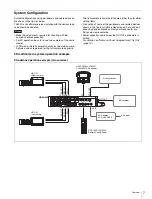
Page 7: ...devices please contact your Sony dealer or a Sony sales representative Power capacity supplied from the DC OUT connectors is limited For details see Notes on Power Supplied from This Unit page 14 3D multicamera system operation example Standalone operation example two cameras Notes CAM MAIN L REF OUT SDI IN CAM SUB R SDI1 OUT SDI2 OUT TEST OUT AUX CRANE TRACKER RET CTRL DC OUT 0 5A max DC OUT 4A m...

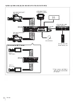
Page 8: ... L DC OUT DC IN AUDIO IN 2 AUDIO IN 1 PROMPTER1 GENLOCK IN REF OUT SDI IN MIC MIC LINE OFF 48V AES EBU LINE OFF 48V INTERCOM DC OUT REF OUT SDI IN DC OUT REF OUT SDI IN REMOTE REMOTE CAM SUB R CAM MAIN L DC OUT REF OUT SDI IN DC OUT REF OUT SDI IN CAM SUB R CAM MAIN L VF SDI2 OUT Optical fiber cable RCP 1500 1501 1530 Remote Control Panel HDCU1000 HKCU HB10 Camera Control Unit HDFA 200 Intercom he...

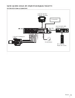
Page 9: ...DIO IN 1 PROMPTER1 GENLOCK IN CAM MAIN L REMOTE CAM SUB R REMOTE REMOTE VF REF OUT SDI IN MIC MIC LINE OFF 48V AES EBU LINE OFF 48V 60 5 6 8 11 16 CL 2 8 2 1 6 T ff 4 30 20 15 12 10 8 7 6 5 6 5 4 6 SDI IN CAM SUB R DC OUT REF OUT SDI IN REMOTE CAM MAIN L INTERCOM VF SDI2 OUT RCP 1000 series Remote Control Panel Intercom headset Optical fiber cable HDCU1000 HKCU HB10 Camera Control Unit Picture mon...

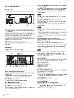
Page 10: ...rom the Memory Stick Only a Memory Stick of Duo size can be used with the camera When the access lamp is lit in red do not insert remove the Memory Stick Duo or turn off the camera For details on Memory Stick see Using a Memory Stick page 35 g CAMERA POWER switch and indicator CCU To operate on power supply via the connected CCU OFF Not to supply power EXT To operate on power supply through the DC...

Page 11: ...cameras SPLIT To display the pictures from the main left and sub right cameras on a split screen DIFF To display difference between the pictures from the main left and sub right cameras CAM HD PROMPT switch Select a picture to be displayed on the viewfinder screen CAM To display the picture from the cameras connected to the unit The displayed picture is selected with the L BOTH R and MIX SPLIT DIF...

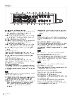
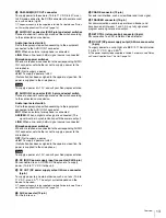
Page 12: ...e signal of input 1 is output from this connector GENLOCK IN For input of an external gen lock signal BB or 3 level sync when the camera is used as a standalone device Even when a BB signal is used for the external sync signal no subcarrier phase lock function is available for the VBS output signal g CAM MAIN L REMOTE connector 8 pin For transmitting the control signal with the camera Connect this...

Page 13: ...connected The signal must be in synchronization with the camera output LINE When a line level 0 dBu signal source is connected Microphone power switches When a microphone is connected to the corresponding AUDIO IN 2 connector set whether or not to supply a power to the microphone OFF Not to supply a power 48V To supply a power of 48 V No function has been assigned to the uppermost position No powe...

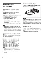
Page 14: ...l fiber cable length 1600 m 5248 ft max 9 A Optical fiber cable length 1200 m 3936 ft max 12 A Optical fiber cable length 1100 m 3608 ft max 13 A When connecting to an HDCU1500 Optical fiber cable length 1100 m 3608 ft max 6 A Optical fiber cable length 700 m 2296 ft max 8 A Optical fiber cable length 200 m 656 ft max 9 2 A Optical fiber cable length 50 m 164 ft max 10 A The above values are merel...

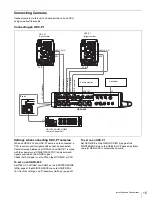
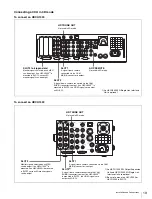
Page 15: ...IVERSAL For the other settings see Preparatory Settings page 22 To set on an HDC P1 Set GENLOCK on the GENLOCK M13 page of the MAINTENANCE menu to ENABLE HV Phase adjustment value for GENLOCK is automatically invalid CAM MAIN L REF OUT SDI IN CAM SUB R SDI1 OUT SDI2 OUT TEST OUT AUX CRANE TRACKER RET CTRL DC OUT 0 5A max DC OUT 4A max CAM SUB R DC OUT CAM MAIN L DC OUT DC IN AUDIO IN 2 AUDIO IN 1 ...

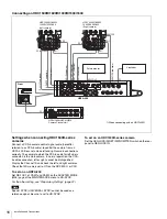
Page 16: ...PROMPTER switch on the rear panel to GENLOCK IN CAM MAIN L REF OUT SDI IN CAM SUB R SDI1 OUT SDI2 OUT TEST OUT AUX CRANE TRACKER RET CTRL DC OUT 0 5A max DC OUT 4A max CAM SUB R DC OUT CAM MAIN L DC OUT DC IN AUDIO IN 2 AUDIO IN 1 PROMPTER1 GENLOCK IN CAM MAIN L REMOTE CAM SUB R REMOTE REMOTE VF REF OUT SDI IN MIC MIC LINE OFF 48V AES EBU LINE OFF 48V OFF 48V MIC FRONT MIC DC OUT AUDIO IN CH1 CH2 ...

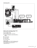
Page 17: ...FIGURATION menu CAM MAIN L REF OUT SDI IN CAM SUB R SDI1 OUT SDI2 OUT TEST OUT AUX CRANE TRACKER RET CTRL DC OUT 0 5A max DC OUT 4A max CAM SUB R DC OUT CAM MAIN L DC OUT DC IN AUDIO IN 2 AUDIO IN 1 PROMPTER1 GENLOCK IN CAM MAIN L REMOTE CAM SUB R REMOTE REMOTE VF REF OUT SDI IN MIC MIC LINE OFF 48V AES EBU LINE OFF 48V OFF ON REMOTE 2 3 M S MO SD AUD IO IN CH 2 LINE MIC 48V ON CH 1 LINE MIC 48V O...

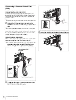
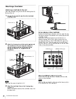
Page 18: ... is made correctly and power is supplied to the unit the CAMERA POWER indicator on the unit and the POWER indicator on the CCU light in green Using the cable clamp belt When a cable clamp belt supplied to the unit an optical fiber cable can be fastened to the front panel of the unit 1 Insert the belt bracket into the upper loop of the cable clamp belt and secure the cable clamp belt to the camera ...

Page 19: ...the CAM MAIN L connector is output HD TRUNK OUT Not used in 3D mode 1 An HKCU2005 3G Single Link Interface Unit is optional HD TRUNK OUT HD PROMPTER IN HD TRUNK OUT Not used in 3D mode SLOT1 A signal from a camera connected via the CAM MAIN L connector is output SLOT22 A signal from a camera connected to the CAM SUB R connector is output If an HKCU20051 is mounted in SLOT2 the L R 3D signals are o...

Page 20: ...tions can also be operated with the switches in the VF SOURCE block on the rear panel without using menu operation When the DISPLAY switch is set to ON Items set to ON using the menu or related switches on the camera will be displayed When an F35 is connected set zoom position focus position and shutter ECS not to be displayed Note AUX CRANE TRACKER RET CTRL DC OUT 0 5A max R1 N CAM MAIN L REMOTE ...

Page 21: ...1 is indicated For the functions that can be assigned see OPERATION menu SWITCH ASSIGN page 30 b Format indication The current video format is displayed c indication area This area is used to display abnormal statuses using the IND function Display options can be set using the menu For details see OPERATION menu IND page 29 d Light receiving level indications This area shows the light receiving le...

Page 22: ... setting on an MSU or RCP Set it on the Configuration screen as described below 1 Display the Configuration screen Config screen for an RCP 2 Select 3D System 3 Select 3D Mode 4 Set 3D Mode to ON To display the 3D support menu on an MSU or RCP Set it on the Configuration screen as described below 1 Display the Configuration screen Config screen for an RCP 2 Select MSU RCP for an RCP 3 Select Secur...

Page 23: ... Picture Inverting Function for a Rig In 3D mode pictures from the left and right cameras can be inverted vertically or horizontally to suit the 3D rig to which cameras are mounted For a camera without the picture inverting function pictures are inverted with the circuit in the HDFA 200 For a camera that has the picture inverting function such as an HDC P1 the camera s inverting function is contro...

Page 24: ...d INTERCOM DISPLAY ASSIGNABLE PROD ENG PGM2 VF SOURCE MIC ON BOTH MIX SPLIT DIFF CAM HD PROMPT L R OFF PTT ON OFF MENU PGM1 RET1 RET 2 3 4 Rear panel DISPLAY switch Menu control knob TOP MENU USER USER MENU CUSTOMIZE ALL OPERATION MAINTENANCE FILE DIAGNOSIS Menu Purpose USER This menu can include menu pages selected from among the OPERATION MAINTENANCE FILE and DIAGNOSIS menus for convenience Chan...

Page 25: ...nob Another cursor appears on the character list 2 Set the cursor to the character to be entered and push on the menu control knob Repeat steps 1 and 2 By selecting INS on the line below the character list you can enter a space at the cursor position Selecting DEL deletes the character at the cursor position You can return to step 1 without changing the character by selecting RET If you enter the ...

Page 26: ...or the previous step then push on the menu control knob The EDIT FUNCTION screen appears 4 Move the pointer to INSERT and push on the menu control knob The page with the last item added appears 5 Add the items 1 Turn the menu control knob until the page that has the desired items appears then push on the menu control knob 2 Turn the menu control knob to move the pointer to the desired item then pu...

Page 27: ...he menu control knob to select the page 3 Move the pointer to the position where you wish to add the page then push on the menu control knob The EDIT FUNCTION screen appears 4 Select INSERT then push on the menu control knob The selection screen appears 5 Move the pointer to the desired page then push on the menu control knob This adds the number and name of the selected page above the item select...

Page 28: ...ges that have been registered on the USER menu at the factory the USER menu page numbers are indicated in parenthesis Execute by ENTER Execute by pushing on the menu control knob ITEM MOVE xx 01 VF OUT 02 VF DETAIL 03 FOCUS ASSIST c04 VF DISPLAY 05 IND 06 VF MARKER 07 CURSOR 08 ZEBRA z09 SWITCH ASSIGN 10 POWER SAVE ESC Note Page title Page No Item Settings VF DISPLAY 01 U05 1 Status of CAM L 2 Sta...

Page 29: ...gs of the VF SOURCE switches SPLIT HORIZONTAL L R VERTICAL L R VERTICAL R L MIRROR SIDE BY SIDE TOP AND BOTTOM POSITION 99 to 99 0 MIX NORMAL DUAL PICT ANAGLYPH LINE ALTE1 LINE ALTE2 DUALPICT DIFF CAM1 CAM2 CAM2 CAM1 CAM CHROMA ON OFF SPLIT LINE ON OFF MESSAGE ON OFF Page title Page No Item Settings VF MARKER 04 U07 MARKER ON OFF WHITE BLACK DOT CENTER ON OFF 1 2 3 4 1 Entire cross 2 Entire cross ...

Page 30: ... SW ENG PROD VF DETAIL MIX VF 5600K FAN MAX VF SCAN CURSOR MARKER Page title Page No Item Settings HEAD SET 11 U11 INTERCOM MIC DYNAMIC CARBON MANUAL LEVEL 60 40 20 dB 60 dB Settings in With DYNAMIC or CARBON cannot be changed 6 0 6 dB Input gain POWER ON OFF ON OFF Settings in With DYNAMIC or CARBON cannot be changed UNBAL ON OFF ON OFF Settings in With CARBON cannot be changed INTERCOM LEVEL 12 ...

Page 31: ...OFF ADAPTER MODE M05 U14 3D MODE ON OFF CAM1 REF OUT HD SYNC UNIVERSAL COMMAND ENABLE CAM2 REF OUT HD SYNC UNIVERSAL COMMAND ENABLE 1 2 3 4 5 6 OUTPUT FORMAT M06 U15 CURRENT Displays the current format ACTIVE LINE Not displayed when a CCU connected JN SY model 1080 59 94i 1080 50i 1080 29 97PsF 1080 25PsF 1080 23 98Psf 1080 24PsF 720 59 94P 720 50P CE E33 model 1080 59 94i 1080 50i 1080 29 97PsF 1...

Page 32: ...L 1 L NORMAL R NORMAL 2 L H Invert R NORMAL 3 L V Invert R NORMAL 4 L HV Invert R NORMAL 5 L NORMAL R H Invert 6 L NORMAL R V Invert 7 L NORMAL R HV Invert 8 L HV Invert R HV Invert 9 L H Invert R HV Invert 10 L V Invert R HV Invert 11 L HV Invert R H Invert 12 L HV Invert R V Invert in 2D mode H MIRROR OFF ON V MIRROR OFF ON in 3D 2D mode V PHASE STATUS CAM1 V STATUS MATCH UNMATCH CAM2 V STATUS M...

Page 33: ...tings Page title Page No Item Settings Default OPERATOR FILE F01 READ MS CAM Execute by ENTER To read the operator file from a Memory Stick WRITE CAM MS Execute by ENTER To write the current settings of the operator file items to a Memory Stick PRESET Execute by ENTER To set the operator file items to the preset values in internal memory STORE PRESET FILE Execute by ENTER To store the current sett...

Page 34: ... body or panels of the unit become dirty wipe them with a dry cloth For severe dirt use a soft cloth steeped in a small amount of neutral detergent then wipe dry Do not use volatile solvents such as alcohol or thinners as these may damage the finish FILE CLEAR F04 PRESET OPERATOR Execute by ENTER 10 SEC CLEAR ON OFF To activate deactivate the function to clear the current menu item See Returning a...

Page 35: ... Slide the switch upward to the write protect position This ensures that you cannot inadvertently overwrote data on the Memory Stick When using Memory Stick media that does not have a LOCK switch be careful not to inadvertently overwrite or erase your data Precautions Do not attach anything other than the supplied label to the Memory Stick labeling position Attach the label so that it does not sti...

Page 36: ... Sony Corporation General Power requirements 240 V AC 1 2 A max 180 V DC 1 1 A max 12 V DC 10 A max Operating temperature 20 C to 45 C 4 F to 113 F Storage temperature 20 C to 60 C 4 F to 140 F Mass Approx 3 8 kg 8 lb 6 oz the main unit only Input output connectors CCU Optical electrical multi connector 1 CAM MAIN L SDI IN CAM SUB R SDI IN BNC type 1 each CAM MAIN L REF OUT CAM SUB R REF OUT BNC t...

Page 37: ... der Kamerasteuereinheit LEMO EDW 3K 93C TLC an CCU Anschluss an einer HDFA 200 Vorsichtsmaßregeln für optische elektrische FBAS Kabel Für Verbindung zwischen Kamerasteuereinheit und einer HDFA 200 verwenden Sie immer ein optisches elektrisches FBAS Kabel mit Steckern wie in dieser Anleitung beschrieben um die Grenzwerte der geltenden EMV Vorschriften zu erfüllen ...

Page 38: ...1 2 90 35 8 4 M4 thread depth max 5 M5 thread depth max 5 6 M4 thread depth max 5 M5 thread depth max 5 10 M4 thread depth max 5 5 3 8 16UNC thread depth max 10 2 M5 thread depth max 5 5 10 hidden holl 152 4 6 228 6 9 266 3 101 2 50 8 2 25 4x5 101 6 1x4 4 266 1 101 2 37 4 11 2 326 127 8 25 4 1 30 13 16 348 133 4 210 83 8 396 155 8 51 4 21 8 152 6 304 12 29 4 13 16 231 6 91 8 37 11 2 12 4 1 2 120 4...

Page 39: ...ol on the CAM Ctrl tab The same selection can be made on the 3D CAM Control page of the Configuration menu Setting the 3D Mode 1 Select 3D System on the Configuration menu screen 2 Select 3D Mode 3 Set 3D Mode to ON Exit Maintenance Camera Lens CCU SD Adjustings VCS 3D Monitor 1 1 Phase Clear Select Mode CAM Ctrl Monitor Output 3D Monitor Exit Left 3D Monitor Right 14 Position CCU 3D Monitor 1 1 P...

Page 40: ...ween the two cameras If Left Only or RIght Only is selected specified items of the selected camera can be controlled The 3D Camera Control function enables setting the switches for this function on the panel 1 Select 3D System on the Configuration menu screen 2 Select 3D CAM Control 3 Select a camera to be controlled Exit 3D Mode ON 3D Mode Exit Configuration Camera CCU MSU CNU RCP Assignment Mult...

Page 41: ...41 Appendices The same selection can be made with 3D Monitor on the CCU page of the Maintenance menu Exit 3D CAM Control Left Only Both Right Only 3D Camera Control ...

Page 42: ...DAPTER CALL RELAY SETTING CCUtCAM ADAPTERtCAM ADAPTER MODE M05 CAM1 REF OUT COMMAND CAM2 REF OUT COMMAND 3D MODE VF DISPLAY 01 EX ZOOM DISP ND CC 5600K IRIS GAIN SHUTT BATT RETURN TALK MESSAG IND 02 ND CC 5600K SHUTT FAN EXT FORMAT VF SOURCE 03 CAM SEL SPLIT POSITION MIX DIFF CAM CHROMA SPLIT LINE MESSAGE VF MARKER 04 MARKER CENTER SAFETY ZONE EFFECT ASPECT MASK SAFETY VF DETAIL 05 VF DETAIL CRISP...

Page 43: ...FORMAT FILE OPERA P F SCENE S REFE FILE C DIAGNOSIS BOAR PLD RO SERI OPTICAL LEVEL D01 CCUtCAM CAMtCCU COM STATUS D02 CAM1 CAM2 RM CCU CHARACTER EMB AUDIO 1 MIC1 2 MIC2 3 AES1 4 AES2 1 PGM1 2 PGM2 3 ENG 4 PROD POWER SAVE RIG IMAGE INVERTER M10 H MIRROR V MIRROR CAM1 V STATUS CAM2 V STATUS V PHASE STATUS POWER SAVE M11 SDI 2 OUT DOWN CONVERTER TRUNK M12 IF TRUNK GENLOCK M13 REFERENCE GENLOCK STATUS...

Page 44: ......

Page 45: ... for use by the purchasers of the equipment described in this manual Sony Corporation expressly prohibits the duplication of any portion of this manual or the use thereof for any purpose other than the operation or maintenance of the equipment described in this manual without the express written permission of Sony Corporation ...

Page 46: ...Sony Corporation HDFA 200 CE E33 JN SY 4 260 395 02 1 Printed in Japan 2017 02 08 2010 ...

Reviews: