10-34
Chapter 10 Setup Operations
10
Setup Operations
Settings for the DME LINK™ Function
– 725
This menu provides settings related to the control of a transition
and the width of the border of a DME wipe pattern with the fader
lever when using the DME LINK™ (DME wipe) function on a
digital video switcher connected to the DME.
With the third set of soft key indications shown in the SETUP &
DIAG menu, press F5 (DME LINK) to display the DME LINK
menu.
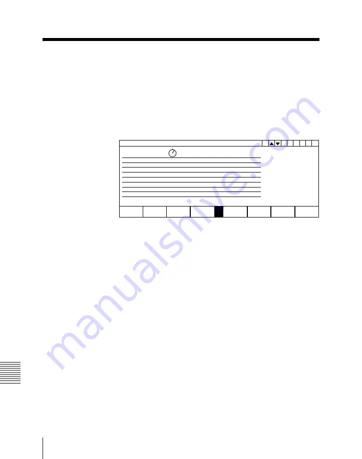
725 DME LINK
Border Type
Trans Range
Border width
Mode 2
•
Mode 1
•
Rnge 12.34
Wdth 34.56
BORDER
TYPE
Rnge
E
G 1 2
R
0
DME LINK menu
Selecting the transition and border width control mode – F1
(BORDER TYPE)
Press F1 (BORDER TYPE) to select the mode.
Mode 1: Regardless of the position of the fader lever, it controls
both the transition and border width.
Mode 2: At either end of the travel of the fader lever, it controls
only the border width, and in the center portion of its travel it
controls only the transition.
When you select “Mode 2”, you can select the portion of the travel
of the fader lever which controls only the transition, by the
following settings.
Align the cursor on “Trans Range”, and turn the left knob
(“Rnge”) to adjust the parameter. (50.00 to 100.00)
For example, setting a value of 80.00 means that 10% of the travel
from either end controls only the border width, and the center 80%
of the travel controls only the transition.
Setting the maximum border width
To set the maximum width of the border of a DME wipe pattern,
align the cursor on “Border Width”, and turn the left knob
(“Wdth”) to adjust the parameter. (0.00 to 100.00)


