12 (E)
-
AC IN
A1
-
AC IN
A2
U
-
AC IN
B1
-
AC IN
232-264CH
IN 1
IN 2
OUT 2
IN 2
OUT 2
IN 2
OUT 2
IN 2
OUT 2
IN 2
OUT 2
IN 2
OUT 2
IN 2
OUT 2
IN 2
OUT 2
256-272CH 239-255CH 222-238CH 205-221CH 188-204CH 171-187CH 154-170CH 137-153CH
120-136CH 103-119CH
86-102CH
69-85CH
52-68CH
35-51CH
18-34CH
1-17CH
DATA
ALARM
REMOTE 3
REMOTE 2
REMOTE 1
REF IN
D
C
B
D
C
B2
B1
A
A
A
B
CASCADE
IN
239-272CH
OUT 1
199-231CH
IN 1
205-238CH
OUT 1
166-198CH
IN 1
171-204CH
OUT 1
133-165CH
IN 1
137-170CH
OUT 1
100-132CH
IN 1
103-136CH
OUT 1
67-99CH
IN 1
69-102CH
OUT 1
34-66CH
IN 1
35-68CH
OUT 1
1-33CH
IN 1
1-34CH
OUT 1
B2
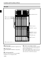
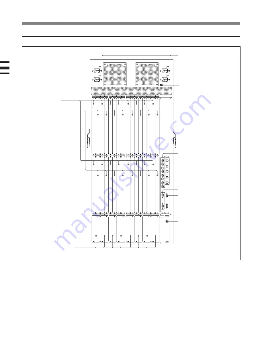
Locations and Functions of Parts
Rear panel
1
Input panel slots
For the optional HKS-5810M/SD 33 Input Board Sets.
2
Output panel slots
For the optional HKS-5860M/SD 34 Output Board
Sets.
3
Cascade input panel slots
For the wire assembly boards of the optional HKS-
5811M/SD 34 Cascade Input Board Sets.
4
AC IN (AC power input) receptacles
There are two pairs of receptacles (A1/A2 and B1/B2).
Connect each receptacle to an AC outlet using an AC
power cord (sold separately).
Two AC power supply units A1 and B1 back up each
other, and A2 and B2 back up each other. Be sure to
make connections to all the four receptacles.
qa
DATA connector
4
AC IN receptacles
5
U
(signal ground) terminal
0
ALARM connector
1
Input panel slots
6
REF IN connectors
7
REMOTE 1 connectors
8
REMOTE 2 connectors
9
REMOTE 3 connector
3
Cascade input panel slots
2
Output panel slots


