background image

Using the Menu

22

03

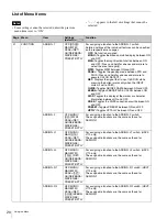
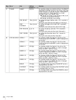
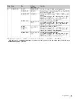
PEAKING

HUE WIDTH

99 to 

[0]

 to 99

For specifying the hue range of which edge enhancement is 
to be performed.

SAT WIDTH

99 to 

[0]

 to 99

For specifying the saturation range of which edge 
enhancement is to be performed.

FREQUENCY

L/

[M]

/MH/H

For specifying the center frequency of edge enhancement 
signals.

RANGE

1 to 

[2]

 to 3

For specifying the variability of edge enhancement level.

04

MAGNIFICATION

MAGNIFICATION

[OFF]

/ON

For selecting normal display (OFF) or magnified display 
(ON).
Normal display (OFF) is selected whenever the power is 
turned on.

MODE SEL

[MODE1]

/MODE2/

MODE3

For selecting a magnification mode.

MAG 
POSITION 

a)

[CENTER]

/

UPPER/RIGHT/
LOWER/LEFT

For selecting the area to magnify when the magnification 
mode is enabled.
The “MAG POSITION” setting is linked to the “POSITION” 
setting of the PEAKING menu.

CENTER:

 Magnifies the center area.

UPPER:

 Magnifies the upper area.

RIGHT:

 Magnifies the right area.

LOWER:

 Magnifies the lower area.

LEFT:

 Magnifies the left area.

DISPLAY 
POSITION

LEFT/

[RIGHT]

For selecting the magnified display (sub display) position 
When “MODE2” is selected in “MODE SEL.”

LEFT:

 Displays the sub display in the lower left of the 

screen.

RIGHT:

 Displays the sub display in the lower right of the 

screen.

AUTO RELEASE

[AUTO]

/MANUAL

For specifying the manner in which the magnified display 
returns to normal display.

AUTO:

 After the magnified display appears by pressing 

ASSIGN. switch, the display returns to normal 
automatically after the specified time.

MANUAL:

 After the magnified display appears by 

pressing ASSIGN. switch, the display returns to normal 
when ASSIGN. switch is pressed again.

05

GUIDE FRAME

GUIDE FRAME

[OFF]

/ON

Toggles between the normal display (OFF) and the guide 
frame display (ON).

PATTERN SEL

[3X3]

/5X5/9X9

Selects the cell display pattern for the guide frame.

COLOR

[W]

/R/G/B/YL

Selects the display color for the guide frame.

LEVEL

1

 to 

[5]

 to 10

Sets the display level of the guide frame. 
Raising the value increases the brightness.

Page

Menu

Item

Settings 
(default in 

[      ]

)

Function

Summary of Contents for HDVF-L750

Page 1: ...LCD COLOR VIEWFINDER HDVF L750 HDVF L770 OPERATION MANUAL English 1st Edition ...

Page 2: ...on 10 Adjusting the Height and Tilting Panning 10 Adjusting the Front Back Position HDVF L770 only 12 Adjusting the Screen 13 Attaching Accessories 14 Attaching a Hood 14 Attaching a Number Plate 15 Using the Focus Assist Function 15 PEAKING PLUS Function 15 MAGNIFICATION Function 17 Using the Menu 18 Basic Menu Operations 18 List of Menu Items 20 Error Message 26 Specifications 26 ...

Page 3: ...to turn off the power of the connected equipment before performing maintenance The surface of the screen is specially coated Do not attach adhesive objects such as stickers on it The surface of the screen is specially coated Do not touch the screen directly Wipe the screen surface gently with a soft dry cloth to remove dirt Stubborn stains may be removed with a soft cloth slightly dampened with a ...

Page 4: ...king and chroma levels can be preset for selection through an assignable switch or a menu operation False color function Display signal levels using different colors When you use the false color function image signals are displayed in black and white and colors are added based on the signal levels Assignable switch Assignable switches are provided on the front 2 switches and on the left and right ...

Page 5: ...rts and Controls 5 Functions of Parts and Controls qh qj ql qk 8 9 qa 67 4 3 5 2 1 0 wa w qd qs qf qg wk wf ws wh wd wg wj wl ea e HDVF L770 qh qj ql qk 8 9 qa 67 4 3 5 2 0 w qd qs qf wk wf ws wh wd wg e es HDVF L750 ...

Page 6: ...dicator begins flashing The threshold battery voltage value at which this indicator begins flashing can be set by the camera For details refer to the manual for the camera iBRIGHT control Adjusts the brightness of the viewfinder image This control does not affect the output signal of the camera jCONTRAST control Adjusts the contrast of the viewfinder image This control does not affect the output s...

Page 7: ...ng the supplied connecting cable 20 pin When you connect the unit to peripheral device use the supplied cable to prevent malfunction due to radiation noise Use a round type 20 pin connector when connecting to the CA4000 ySDI IN connector BNC type When using monitor mode connect this to the SDI OUT connector on the camera or external device using a BNC cable For details on supported formats see Spe...

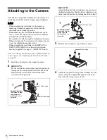
Page 8: ...n of the viewfinder attached to the camera see Adjusting the Viewfinder Position on page 10 1 Reset the viewfinder to the standard position 2 HDVF L770 Fix the viewfinder screen in the standard position by turning the tilt lock knob and lift lock knob in the direction of the arrow indicated on each knob toward the lock position HDVF L750 Adjust the height of the viewfinder to the position of the i...

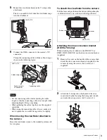
Page 9: ...e viewfinder attached to the camera Reset the viewfinder screen to the standard position and fix it in place To detach the viewfinder from the camera Pull the lever and push down the button while pulling the viewfinder toward you as shown in the figure below Attaching the shoe conversion bracket HDVF L750 only When attaching the viewfinder to the HXC D70 or PMW 320 350 400 500 use the shoe convers...

Page 10: ...r height and tilt or pan the viewfinder HDVF L770 1 Turn the tilt lock knob and lift lock knob in the direction of the arrow shown below to unlock 2 Turn the tilt friction adjustment knob and lift friction adjustment knob in the direction of the arrow shown below to adjust the friction Turn the COUNTER BALANCE control to adjust the counterbalance for the screen if necessary Lift lock knob Tilt loc...

Page 11: ...See page 12 4 Turn the tilt lock knob and lift lock knob in the direction of the arrow indicated on each knob toward the lock position to secure the position of the viewfinder HDVF L750 1 Adjust the height of the viewfinder by loosening the lift fixing screw then fix it by fastening The height of the viewfinder can be adjusted in 2 levels Loosen the lift fixing screw while holding the viewfinder s...

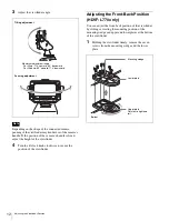
Page 12: ...djusting the Front Back Position HDVF L770 only You can adjust the front back position of the viewfinder by sliding or rotating the mounting position of the mounting wedge and upper and lower plates at the bottom of the viewfinder 1 Holding the viewfinder firmly remove the seven screws from the mounting wedge and the lower plate Note Tilting adjustment Panning adjustment Maximum adjustment range F...

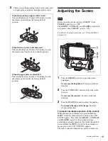
Page 13: ...a clockwise direction To prevent accidental operation of the controls When the menu is not displayed press and hold the MENU switch for three seconds or more so that VR LOCK appears This locks the BRIGHT CONTRAST and PEAKING controls at their current settings preventing accidental operation To unlock the controls press and hold the MENU switch for three seconds or more again so that VR UNLOCK appe...

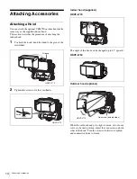
Page 14: ...d to the groove the viewfinder 2 Tighten the screw to fix the viewfinder Indoor hood supplied HDVF L770 The angle of the hood can be changed up to 45 upward HDVF L750 Outdoor hood optional When the outdoor hood is too tight to move or too loose to fix at a desired position adjust the coin screws on both sides of the hood Turn the screws clockwise to tighten and counterclockwise to loosen Groove HD...

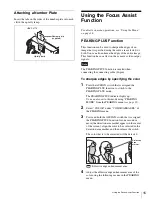
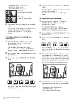
Page 15: ...g the color 1 Press the ASSIGN switch that is assigned the PEAKING PLUS function to switch to the PEAKING PLUS mode The PEAKING PLUS indicator lights up You can also set to this mode using PEAKING MODE from the PEAKING menu see page 21 2 Select COLOR under COLOR AREA SEL of the PEAKING menu 3 Press and hold the ASSIGN switch that is assigned the PEAKING PLUS function for one second or more the det...

Page 16: ...y the edges of the object within the area selected in step 3 will be sharpened Turn the control clockwise to make the edges sharper To specify both color and area 1 Press the ASSIGN switch that is assigned the PEAKING PLUS function to switch to the PEAKING PLUS mode The PEAKING PLUS indicator lights up You can also set to this mode using PEAKING MODE from the PEAKING menu see page 21 2 Select BOTH...

Page 17: ...he image is magnified You can also set to this mode from the MAGNIFICATION menu see page 22 2 Press and hold the ASSIGN switch that is assigned the MAGNIFICATION function The magnified area changes in the following sequence You can also select an area under MAG POSITION of the MAGNIFICATION menu see page 22 If the MAG POSITION setting is changed the POSITION setting in the PEAKING menu will be cha...

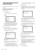
Page 18: ... move the c mark upward turn the control counterclockwise Position the c mark to the left of the desired menu item and then press the MENU control A mark appears to the left of the setting and the settings screen is activated value setting mode To select another menu item press the MENU switch to return to item select mode 4 Change the value of a setting With the mark positioned to the left of the...

Page 19: ...returns to item select mode 6 Set other menu items Repeat steps 2 to 5 to set other menu items 7 End menu operations Press the MENU switch repeatedly until the menu page disappears from the display To restore a setting to its factory default value Position the c mark to the left of the desired menu item or while the mark appears to the left of the menu item to be restored press the MENU control fo...

Page 20: ...tween ON and OFF DISP Toggles the display of the marker or character information between ON and OFF KNEE Toggles the KNEE correction circuit between ON and OFF PRESET Toggles PRESET between ON and OFF UPTLY Toggles UP TALLY between ON and OFF ASSIGN 2 OFF MONO MAG WFM PEAK RET GUIDE ZEBRA DISP KNEE PRESET UPTLY For assigning a function to the ASSIGN 2 switch The assignable functions are the same a...

Page 21: ...er tally indicators LOWER Activates the indicators including the lower tally indicators except the upper tally indicators TALLY IND DIM 1 to 5 to 10 For setting the brightness of the indicators including the tally indicators Raising the value increases the brightness lowering the value decreases the brightness 03 PEAKING PEAKING MODE STD PLUS For selecting a peaking mode STD Standard mode PLUS PEA...

Page 22: ...he right area LOWER Magnifies the lower area LEFT Magnifies the left area DISPLAY POSITION LEFT RIGHT For selecting the magnified display sub display position When MODE2 is selected in MODE SEL LEFT Displays the sub display in the lower left of the screen RIGHT Displays the sub display in the lower right of the screen AUTO RELEASE AUTO MANUAL For specifying the manner in which the magnified displa...

Page 23: ...itor LINE Displays the video level at any point on the horizontal axis of the image FIELD Displays the video level at any point on the vertical axis of the image LINE SELECT OFF ON For selecting the waveform monitor display for all lines OFF or for the selected LINE ON when LINE is selected in SWEEP LINE 0 to 50 to 100 For setting the position of selected LINE when ON is selected in LINE SELECT In...

Page 24: ...er the changes in the status of the function assigned to the ASSIGN 1 switch is displayed ON or not OFF ASSIGN 2 OFF ON For selecting whether the changes in the status of the function assigned to the ASSIGN 2 switch is displayed ON or not OFF ASSIGN L1 OFF ON For selecting whether the changes in the status of the function assigned to the ASSIGN L1 switch is displayed ON or not OFF HDVF L770 only A...

Page 25: ...s set to SDI When the INPUT switch is set to CAM perform the ZEBRA setting on the menu of the camera ZEBRA1 LEVEL 50 to to 107 Sets the level that displays ZEBRA1 This function works only when the INPUT switch is set to SDI When the INPUT switch is set to CAM perform the ZEBRA setting on the menu of the camera ZEBRA1 APERTURE LEVEL 1 to to 20 Sets the aperture level for ZEBRA1 This function works ...

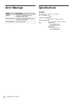
Page 26: ...re 0 C to 45 C 32 F to 113 F Storage temperature 20 C to 60 C 4 F to 140 F Mass HDVF L770 3 0 kg 6 lb 9 8 oz not including hood HDVF L750 1 7 kg 3 lb 12 oz not including hood Display Description ERROR Failure in COLOR DETECT in PEAKING PLUS mode BACKUP ERROR Checksums of the EEPROM backup data are not consistent DEVICE ERROR Other device errors ...

Page 27: ...atio Performance Brightness 300 cd m2 typical Resolution 1920 1080 Color temperature D65 308 6 12 1 4 253 10 167 6 5 8 342 5 13 1 2 310 12 1 4 62 2 1 2 Unit mm inches When the optional VFH 790 is installed HDVF L770 212 8 3 8 295 11 5 8 147 5 7 8 62 2 1 2 310 12 1 4 381 5 15 1 8 Unit mm inches When the optional VFH 790 is installed HDVF L750 ...

Page 28: ... is needed for the HDVF L770 Designs and specifications are subject to change without notice Format Frame rate 1080 59 94P 59 94 1080 50P 50 1080 29 97P 29 97 1080 25P 25 1080 24P 24 1080 23 98P 23 98 1080 59 94i 29 97 1080 50i 25 1080 29 97PsF 29 97 1080 25PsF 25 1080 24PsF 24 1080 23 98PsF 23 98 720 59 94P 59 94 720 50P 50 Color display Signal level Red 105 4 or higher Yellow 102 4 to 105 4 Pink...

Page 29: ... for use by the purchasers of the equipment described in this manual Sony Corporation expressly prohibits the duplication of any portion of this manual or the use thereof for any purpose other than the operation or maintenance of the equipment described in this manual without the express written permission of Sony Corporation ...

Page 30: ...Sony Corporation HDVF L750 SY HDVF L770 SY 4 543 739 11 1 2014 ...

Reviews: