64
Items in the Basic Setup Menu
Chap
ter
9
Set
up Men
u
s
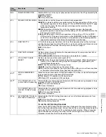
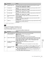
009
a)
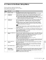
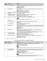
CHARACTER TYPE
Determines the type of characters such as timecode output from the COMPOSITE OUT
2 (SUPER) connector, HD SDI OUTPUT (SUPER) connector, and SDI OUT 2 (SUPER)
connector for superimposed display on the monitor.
[WHITE]:
White letters on a black background
BLACK:
Black letters on a white background
W/OUT:
White letters with black outline
B/OUT:
Black letters with white outline
011
a)
CHARACTER V-SIZE
Determines the vertical size of characters such as timecode output from COMPOSITE
OUT 2 (SUPER) connector, HD SDI OUTPUT (SUPER) connectors, and SDI OUT 2
(SUPER) connector for superimposed display on the monitor.
[
×
1]:
Standard size
×
2:
2 times standard size
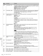
012
CONDITION DISPLAY ON
VIDEO MONITOR
Determines whether the channel condition is superimposed on the superimposed
characters.
[DIS]:
Not displayed
ENA:
Displayed
To display
The channel condition is displayed below the timer or status display.
Example)
V-A-
A character following V indicates the status of the video channel on the rotary head.
A character following A indicates the status of the audio channel on the rotary head.
Character pattern
–:
Good
*
:
Not good
x
:
Bad
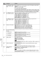
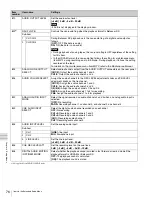
013
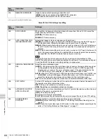
SYSTEM FREQUENCY
SELECT
Specify whether to enable switching of the system frequency between 59.94i, 50i,
29.97PsF, 25PsF, 24PsF, and 23.98PsF.
[OFF]:
Disable switching.
ON:
Enable switching.
When ON is selected, the menu display changes to allow switching of the setting
between 59.94i, 50i, 29.97PsF, 25PsF, 24PsF, and 23.98PsF.
For the procedure for switching the system frequency, see “ Switching the system
frequency (menu item 013)” on page 62.
Notes
• For the basic and extended setup menus, separate settings are saved for 59.94i,
29.97PsF mode, 50i, 25PsF mode, and 24PsF, 23.98PsF mode. When you switch
systems, all menu items change to the settings established in the new system. (The
settings are different from those for the mode before switching.)
• When the unit is used in 50i, 29.97PsF mode, analog tape can only be played back in
the simple playback mode.
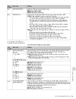
014
SEQUENTIAL RECORD
MODE
Selects the method for sequential recording using two HDW-S280 units.
[OFF]:
No sequential recording
REPL:
For one time sequential recording. Every time a sequential recording ends,
replace a cassette.
OVER:
For repeated sequential recording by overwriting. (No cassette replacement)
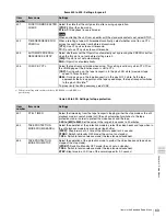
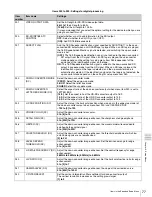
028
HD CHARACTER
Sets whether character information is superimposed or not to the video signal output
from the HD SDI OUTPUT (SUPER) connectors.
[OFF]:
Not superimposed
F-KEY:
Depending on the setting for the function menu.
029
STORED OWNERSHIP
Select whether or not to set the Stored Ownership UMID item.
[OFF]:
Do not set.
ON:
Set.
To set Stored Ownership, see “ Setting Stored Ownership” on page 56.
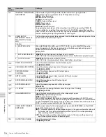
033
BATTERY END VOLTAGE
Sets the voltage to shut down the unit in the battery operation. The battery near end
indicator flashes at +0.7 V of the set voltage.
[10.5V]~13.5V:
10.5 V to 13.5 V in 0.5 V unit.
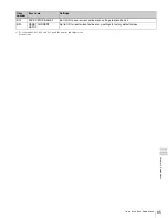
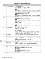
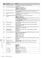
B01
RECALL SETUP BANK 1
Set to ON to recall menu settings from menu bank 1.
B02
RECALL SETUP BANK 2
Set to ON to recall menu settings from menu bank 2.
B11
SAVE SETUP BANK 1
Set to ON to save current active menu settings to menu bank 1.
Item
number
Item name
Settings

