background image

49

Automatic Editing

  Chap

te

r 5

   A
s

s

e

mb
le

 E

d

it

ing

5-2-5  Performing Automatic Editing

Overview

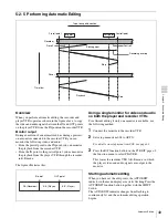
When you perform automatic editing, the recorder and 
player VTRs operate as shown in the figure above, to copy 
the video and audio signals between the IN and OUT points 
on the player VTR from the IN point on the recorder VTR.

Monitor output

During execution of an automatic edit, as during a preview, 
on a monitor connected to the recorder VTR you can 
monitor the following video and audio:
• From the preroll point to the IN point, you can monitor 

the playback from the recorder VTR.

• From the IN point to the postroll point, you can monitor 

the playback from the player VTR through the recorder 
in E-E mode.

The figure illustrates this. 

Using a single monitor for video and audio 
on both the player and recorder VTRs

For efficient editing if only one monitor is available, use 
the following method:

1

Connect the monitor to the recorder VTR.

2

Set setup menu item 008 to AUTO.

For details on setup menu item 008, see page 63.

3

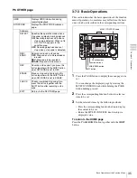
Press the R/P function button on the P5 EDIT page of 
the function menu to select PLAYER.

This forces the recorder VTR to E-E mode, in which 
the player video and audio signals are output to the 
monitor.

Starting automatic editing

When you have set the edit points, the AUTOEDIT 
indicator in the menu display area starts flashing. Press the 
AUTOEDIT function button together with the SHIFT 
button.
The AUTOEDIT indicator changes from flashing to 
continuously lit, and the automatic editing operation 
begins.

Player

Tape transport direction

Preroll point

Recorder

Preroll

Time flow

Playback

Postroll

Postroll point

OUT point

IN point

Edit segment

Stop

Recording overlap

Stop

PB (Recorder)

E-E (Player)

E-E (Player)

IN point

OUT point

Summary of Contents for HDW-S280

Page 1: ...E RECORDER HDW S280 OPERATION MANUAL English 1st Edition Revised 5 The supplied CD ROM includes Operation Manual English French German and Japanese versions in PDF format For details see 1 3 Using the CD ROM Manual on page 12 ...

Page 2: ...sonnel Servicing is required when the apparatus has been damaged in any way such as power supply cord or plug is damaged liquid has been spilled or objects have fallen into the apparatus the apparatus has been exposed to rain or moisture does not operate normally or has been dropped To reduce the risk of fire or electric shock do not expose this apparatus to rain or moisture To avoid electrical sh...

Page 3: ... used to connect peripherals must be shielded in order to comply with the limits for a digital device pursuant to Subpart B of Part 15 of FCC Rules For the customers in Europe This product with the CE marking complies with both the EMC Directive and the Low Voltage Directive issued by the Commission of the European Community Compliance with these directives implies conformity to the following Euro...

Page 4: ...tive sur les basses tensions émises par la Commission de la Communauté Européenne La conformité à ces directives implique la conformité aux normes européennes suivantes EN60065 Sécurité des produits EN55103 1 Interférences électromagnétiques émission EN55103 2 Sensibilité électromagnétique immunité Ce produit est prévu pour être utilisé dans les environnements électromagnétiques suivants E1 réside...

Page 5: ...tromagnetische Verträglichkeit Störfestigkeit Für die folgenden elektromagnetischen Umgebungen E1 Wohnbereich E2 kommerzieller und in beschränktem Maße industrieller Bereich E3 Stadtbereich im Freien und E4 kontrollierter EMV Bereich z B Fernsehstudio Der Hersteller dieses Produkts ist Sony Corporation 1 7 1 Konan Minato ku Tokyo Japan Der autorisierte Repräsentant für EMV und Produktsicherheit is...

Page 6: ...2 3 1 2 Using the Battery Pack 23 3 2 Using a Stand 24 3 3 Connections 25 3 4 Handling Cassettes 26 3 4 1 Usable Cassettes 26 3 4 2 Loading Ejecting Cassettes 26 3 4 3 Preventing Accidental Erasures 26 3 5 Setting Reference Video Signals 27 3 6 Setting Timecode 28 3 6 1 Setting an Initial Value and Recording Timecode 28 3 6 2 Synchronizing the Internal Timecode Generator with an External Signal 29...

Page 7: ...ording 41 4 4 Playback 43 4 4 1 Preparations for Playback 43 4 4 2 Playback Operation 43 4 4 3 Jog Shuttle Mode playback 44 Chapter 5 Assemble Editing 5 1 Overview 45 5 1 1 Assemble Editing 45 5 2 Automatic Editing 45 5 2 1 Setting the Edit Points 45 5 2 2 Modifying and Deleting Edit Points 46 5 2 3 Cueing up to Edit Points and Prerolling 47 5 2 4 Preview 48 5 2 5 Performing Automatic Editing 49 5...

Page 8: ...etup Menu Operations 60 9 2 1 Displaying Setup Menus 60 9 2 2 Setting Setup Menu 61 9 2 3 Menu Bank Operations menu items B01 to B12 62 9 3 Items in the Basic Setup Menu 63 9 4 Items in the Extended Setup Menu 66 Chapter 10 Maintenance and Inspection 10 1 Removing a Cassette When Tape Slack Occurs 79 10 2 Head Cleaning 79 10 3 Error Messages 80 10 4 Warning Messages 82 10 5 Moisture Condensation 8...

Page 9: ...omers in the U S A and Canada The video setup amount is set to 0 at the factory If necessary you can change the amount using setup menu item 713 For details on setup menu item 713 see page 74 Note Video set up amount ...

Page 10: ...picture easily for effective cueing up and editing AC and DC power The unit can be operated with a variety of power sources such as DC power using a battery pack or an AC adaptor and an AC power source Applicable battery packs are the BP GL65 GL95 and BP L60 A L90 A L60S L80S lithium ion batteries and BP M50 M100 nickel hydrate batteries The unit can operate for about 80 minutes with a BP GL95 bat...

Page 11: ... HDW S280 EJECT PUSH PITCH CTL HKDV 900 HD SDI INPUT REMOTE 9P REMOTE 9P REMOTE VIDEO CONTROL HD SDI OUTPUT SDI OUT SP SX HDCAM HDCAM HD SDI OUTPUT SDI OUT AUDIO OUTPUT COMPOSITE OUT AC IN DC IN 12 V AUDIO MONITOR OUT HD SDI OUTPUT INPUT REMOTE 9P AUDIO OUTPUT INPUT HD SDI OUTPUT COMPOSITE OUT AUDIO INPUT PHONES HD camera BVE series editor HKDV 900 video control unita Microphone Analog cassette Di...

Page 12: ...tes and or other countries 1 3 2 Reading the CD ROM Manual To read the operation manual contained on the CD ROM do the following 1 Insert the CD ROM in your CD ROM drive A cover page appears automatically in your browser If it does not appear automatically in the browser double click on the index htm file on the CD ROM 2 Select and click on the operation manual that you want to read This opens the...

Page 13: ...r channel recording level or four channel playback level if you set thie option with setup menu item 826 In this case each knob controls channel indicated below CHARACTR ON PB EE PB CONFI ENABLE CTL TC TC ASSEMBLE OFF TCG SET HOME LTC DF VITC LTC EXT LTC R RUN REM 00M 0 10 20 30 40 1 CH1 IN CH2 IN OUT MONI L MONI R 60 INPUT ANA 4 HD COND P ROLL D STOP BANK 2 DOLBY NR 4 1 2 SDI ASMBL CONFI ON RECOR...

Page 14: ...t those of the STOP and EJECT buttons When two HDW S280 units are connected press this button on the player VTR to make it lit You can determine which tape transport buttons on the front panel are to be enabled when the REMOTE button is lit with setup menu item 006 For details on setup menu item 006 see page 63 2 1 1 Menu Operation Section a Function buttons Select and set menu items displayed in ...

Page 15: ...inues for longer than eight minutes If you operate a search dial or any of the tape transport buttons other than the PAUSE button while the unit is in standby off mode the unit changes to standby on mode and enters the mode called by the button or dial that you pressed By pressing the SHIFT button together with the STOP button you can switch between standby on and standby off mode manually Tape pr...

Page 16: ... direction the G indicator lights Turning the dial counterclockwise plays a tape in the reverse direction the g indicator lights When the tape stops the s indicator lights Setting for setup menu item 101 enables a direct search operation that enables the search dial operation without pressing the JOG SHUTTLE button direct jog shuttle mode For details on setup menu item 101 see page 66 k JOG SHUTTE...

Page 17: ...ed Dolby noise reduction manufactured under license from Dolby Laboratories Licensing Corporation Dolby and the double D symbol are trademarks of Dolby Laboratories Licensing Corporation d Condition area A Format display Displays the format of the cassette in use If you start recording on a Betacam SX Betacam SP or Betacam cassette the cassette mark flashes When a cassette is being ejected the cas...

Page 18: ...setup menu item 214 see page 68 f Timecode setup area A Time data type Displays the type of time data displayed in the time data display area B Drop frame display DF appears when a tape recorded in drop frame mode is played C Timecode type When VITC is read during playback VITC is displayed When LTC is read LTC is displayed During recording the type of timecode being recorded appears In E E mode i...

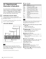
Page 19: ...e DC SQ Squeeze mode of the down convert mode UC EC Edge crop mode of the up convert mode UC LB Letter box mode of the up convert mode UC SQ Squeeze mode of the up convert mode For details on setup menu item 140 see page 67 C Superimposed data Appears when CHARACTR on the HOME page of the function menu is set to ON Picture frame in playback The frame when an SD cassette is played can be selected w...

Page 20: ... Stick slot Insert a Memory Stick h REF INPUT reference video signal input connectors BNC type Input a reference video signal a three valued positive and negative sync signal a video signal with color burst VBS or a black and white video signal VS When the signal is bridged termination is automatically set to OFF Be sure to use the unit for frame synchronization only not for color subcarrier synch...

Page 21: ... setup menu item 028 You can always disable to superimpose the data independent of the setting for CHARACTR with the setting for setup menu item 028 For details on CHARACTR setting see 3 7 Basic Operations of the Function Menu on page 31 For details on the setup menu item 028 see page 64 n HD SDI high definition serial digital interface INPUT connectors BNC type Input the HD SDI format video audio...

Page 22: ...To supply DC power to the unit set the power switch on the front panel to ON and the POWER switch on the rear panel to OFF If the POWER switch on the rear panel is set to ON AC power is supplied Battery power supply The BP GL95 lithium ion battery pack provides up to 80 minutes of continuous recording time and the BP L80S provides up to 55 minutes For details on charging battery packs refer to the...

Page 23: ... pack in it For details on attaching the BKP L551 refer to the installation manual for the BKP L551 1 Remove the two screws on the side panel 2 Attach the BKP L551 to the side panel 3 Align the grooves on the BP GL65 GL95 with the projections on the BKP L551 4 Slide the BP GL65 GL95 as shown below so that the connectors on the BP GL65 GL95 and the BKP L551 are connected 5 Connect the DC cable of t...

Page 24: ...from the clamps and turn it as indicated by the arrow 2 Push the stand in as indicated by the arrow Be sure to push it to the end Replacing the stand Pull the stand out turn it in the opposite direction of that in step 1 above and secure it with the clamps Never hold the unit with the stand Note Clamps Stand ...

Page 25: ... 2 R L 1 2 1 2 MONI OFF POWER DC IN 12V REMOTE VIDEO CONTROL REMOTE 9P AUDIO MONITOR OUTPUT AUDIO OUTPUT AUDIO INPUT SDI OUT COMPOSITE OUT INPUT OUTPUT HD SDI TIME CODE REF INPUT AC IN ON IN 1 SUPER SUPER SUPER IN IOUT 2 1 2 1 1 2 3 1 PUSH PUSH 2 3 2 1 3 2 1 3 2 1 3 2 1 3 2 R L 1 2 1 2 MONI OFF REMOTE 9P REF INPUT AC IN AC IN REMOTE 9P REF INPUT REF INPUT HD SDI OUTPUT HD SDI INPUT Player VTR Reco...

Page 26: ...means that there is condensation inside the unit For the steps to take in such a case see 10 5 Moisture Condensation on page 83 If there is slack in the tape Take up the slack by rotating the reels in the directions indicated by the arrows in the figure keeping one reel fixed by pressing it with your finger as you rotate the other reel The reels stop rotating when there is no more slack Ejecting t...

Page 27: ... 309 and 334 the setting for OUT REF on the P2 VIDEO page of the function menu and the operating mode of the unit For details on setup menu item 309 see page 68 and for item 334 see page 68 For details on the OUT REF settings see 3 7 Basic Operations of the Function Menu on page 31 EE E E mode PB Playback Normal playback jog mode shuttle mode stop mode ASSEMBLE Assemble edit mode ASSEMBLE on the H...

Page 28: ...to INT and PRST RGN to PRESET Recording method TCG setting PRST RGN setting Record the output of the internal timecode generator with the initial value set INT PRESET Record the output of the internal timecode generator synchronized with the external timecode generator EXT or SDI LTC or VITC Record the output of the internal timecode generator synchronized with the playback timecode During editing...

Page 29: ...p 1 of Setting an initial timecode value and Carry out steps 2 to 5 Settings are made in hexadecimal 0 9 A F You can record ID codes in user bits For details see setup menu items 603 and 604 on page 70 3 6 2 Synchronizing the Internal Timecode Generator with an External Signal Use this method to synchronize multiple VTRs with an external timecode generator and when you wish to record the playback ...

Page 30: ...ting you can set then with setup menu item 610 For details on setup menu item 610 see page 71 If you set TCG on the P4 TC page to EXT or SDI and PRST RGN to PRESET PRST RGN is forced to function as LTC 3 6 4 Converting Timecode in 24 or 25 Frame Mode Playback TC CONV When a tape recorded in 24 frame mode is played back in 25 frame mode off speed playback the timecodes for 24 frame mode can be conv...

Page 31: ...DIT P6 OTHER F1 CHARACTR VID PROC VIDEO IN AUDIO IN TCG R P UMID ON OFF LOCAL MENU SDI SG ANALOG SDI SG INT EXT SDI RECORDER PLAYER F2 PB EE VIDEO OUT REF MONITR L PRST RGN IN STOPCODE PB EE PRESET XXXX REF INPUT CH1 CH2 CH3 CH4 CUE PRESET LTC VITC Not displayed Lit Flashinga F3 CONFI CHROMA MONITR R RUN DELETE ENABLE DISABLE PRESET XXXX CH1 CH2 CH3 CH4 CUE FREE REC Not displayed Lit Flashinga F4 ...

Page 32: ...de ON The assemble edit mode is set and ASMBL appears in the display window OFF The assemble edit mode is canceled TCG SET When CTL TC is set to TC a screen for setting the initial value of the timecode generated by the internal timecode generator appears b When CTL TC is set to UB a screen for setting the user bit of the timecode appears b Submenu T t Selects the digit to set data Sets the value ...

Page 33: ...yed setting flashing by pressing the SC function button turn the MULTI CONTROL knob to adjust the output signal sync phase across the range of 200 ns relative to this unit s input reference signal Item Setting Item Setting AUDIO IN Selects an audio input signal The selected signal is shown at INPUT in the audio data area ANALOG Analog audio signal SDI SDI signal SG SG signal MONITR L Selects an ou...

Page 34: ...layer or recorder when two VTRs are connected the VTR connected to the REMOTE 9P connector is used as a player and this unit is used as a recorder For a single VTR operation press the button for more than two seconds RECORDER Controls this unit the recorder VTR PLAYER Controls the connected player VTR IN Sets the current tape point as the IN point when pressed together with the SHIFT button An ind...

Page 35: ...TOP appears in the condition area OFF Recording playback does not stop when a stop code is detected REC ERAS Records or erases a stop code OFF Stop code not to be recorded or erased REC Stop code to be recorded ERASE Stop code to be erased REC Records a stop code if you press this button together with the SHIFT button when REC ERAS is set to REC ERASE Erases a stop code by pressing this button tog...

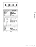
Page 36: ...ates non drop frame mode c Drop frame mark of the timecode generator for 59 94i mode only Indicates drop frame mode factory preset Indicates non drop frame mode d Field mark of VITC data blank Fields 1 and 3 for 59 94i mode or fields 1 3 5 and 7 for 50i mode Fields 2 and 4 for 59 94i mode or fields 2 4 6 and 8 for 50i mode e Selection of recorder player The indication changes as follows according ...

Page 37: ... servo unlocked PLAY LOCK Play mode servo locked PLAY PAUSE Play mode standby REC Record mode servo unlocked REC LOCK Record mode servo locked REC PAUSE Record mode standby JOG STILL Still picture in jog mode JOG FWD Jog in forward direction JOG REV Jog in reverse direction SHUTTLE speed Shuttle mode AUTOEDIT Automatic editing mode PREVIEW Preview mode REVIEW Review mode SEQ REC Sequential record ...

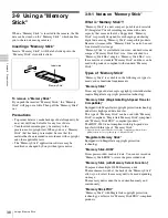
Page 38: ...t Memory Stick Duo size Once attached to a Memory Stick Duo adapter Memory Stick Duo is to the same size as standard Memory Stick and thus can be used with products compliant with standard Memory Stick Types of Memory Stick Memory Stick is available in the following six types to meet various functional requirements Memory Stick Stores any type of data except copyright protected data that require M...

Page 39: ...e data when the write protect tab on the Memory Stick is set to LOCK We recommend backing up important data Image data may be damaged in the following cases If you remove the Memory Stick or turn the power off when the access lamp is lit or flashing If you use a Memory Stick near static electricity or a magnetic field Do not attach anything other than the supplied label to the Memory Stick labelli...

Page 40: ... REC LEVEL adjustment knobs monitoring the input levels indicated by the audio level meter You can set the channels to be controlled with the REC LEVEL adjustment knobs with setup menu item 826 For details on setup menu item 826 see page 76 4 1 2 Recording Operation Confirm that the REC INHI indicator on the front panel is not lit Then follow the procedure below 1 Press the REC and PLAY buttons si...

Page 41: ...orm the front panel operations on the both units during sequential recording Note CHARACTR ON PB EE PB CONFI ENABLE CTL TC TC ASSEMBLE OFF TCG SET HOME LTC DF VITC LTC EXT LTC R RUN REM 00M 0 10 20 30 40 1 CH1 IN CH2 IN OUT MONI L MONI R 60 INPUT ANA 4 HD COND P ROLL D STOP BANK 2 DOLBY NR 4 1 2 SDI ASMBL CONFI ON RECORDER 59 94i EMPH 2 EMPH 0 10 20 30 40 3 EMPH 4 EMPH 00 00 00 00 STANDBY REW PLAY...

Page 42: ...ew cassette into the VTR If you change a cassette during AUTO REW of the sequential recording the VTR continues the sequential recording For details on setup menu item 125 see page 67 To stop sequential recording Sequential recording stops in the following cases When a tape transport button PLAY STOP F FWD REW EJECT is pressed during recording If the cassette is not exchanged when the cassette mar...

Page 43: ...code or the timecode read by the timecode reader can be output via the TIME CODE OUT connector To synchronize the timecode with the output video signal follow the procedures below 1 Set setup menu item 606 to REGEN For details on setup menu item 606 see page 70 2 Set TCG on the P4 TC page of the function menu to INT 3 Set PRST RGN on the P4 TC page of the function menu to LTC or VITC For details o...

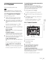
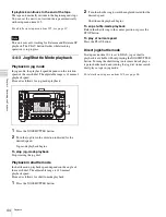
Page 44: ...mode playback 1 Press the JOG SHUTTLE button 2 Turn the shuttle ring toward the angle indicated for the desired speed Shuttle mode playback begins To sop shuttle mode playback Return the shuttle ring to the center position or press the STOP button To play at normal speed Press the PLAY button Direct jog shuttle mode If setup menu item 101 is set to DIAL jog or shuttle playback is available without...

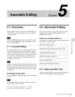
Page 45: ...signal CTL and a timecode must be recorded on the tape in advance of the recorder IN point for a length equal to or greater than the preroll time Selecting assemble mode Set ASSEMBLE on the HOME page of the function menu to ON For assemble editing set TCR on the P4 TC page of the function menu to LTC or AUTO For details on the function menu see 3 7 Basic Operations of the Function Menu on page 31 ...

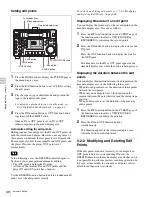
Page 46: ...play the data for the OUT point The time data for the IN or OUT point appear in the time data display area while the button is held pressed Displaying the duration between the edit points You can display the duration between two edit points in the time data display area in the following three cases When two edit points are set the duration of the segment between the two points When only one edit p...
Page 47: ...s finished and PROLL appears at the Jog Shuttle display positon in the condition area of the display window Preroll Press the PREROLL button The tape is wound back to a position five seconds before the IN point and stops Changing the preroll time The factory default setting for the preroll time is five seconds but you can use setup menu item 001 to change this to any value from 0 to 30 seconds If ...

Page 48: ...iew Press the STOP button The tape stops where it was when you pressed the button To return the tape to the preroll point Press the PREROLL button To return the tape to the IN point or OUT point Press the PREROLL button together with the IN or OUT function button on the P5 EDIT page of the function menu Monitor output During a preview on a monitor connected to the recorder you can monitor the foll...

Page 49: ...o on both the player and recorder VTRs For efficient editing if only one monitor is available use the following method 1 Connect the monitor to the recorder VTR 2 Set setup menu item 008 to AUTO For details on setup menu item 008 see page 63 3 Press the R P function button on the P5 EDIT page of the function menu to select PLAYER This forces the recorder VTR to E E mode in which the player video a...

Page 50: ... tape returns to the OUT point To modify the edit points and reexecute the edit after automatic editing Press the DELETE function button together with the SHIFT button to retrieve the edit points After modifying the edit points perform automatic editing again For details of modifying edit points see 5 2 2 Modifying and Deleting Edit Points on page 46 5 2 6 First Edit Function The first edit functi...
Page 51: ...ton The type of the cued up shot mark is indicated in the condition area You can select the type of shot mark to be cued up with setup menu item 630 For details on setup menu item 630 see page 72 Displaying shot data Shot data are the data on recording at each recording Press the PLAY button together with the SHIFT button to display the shot data The tape is played and the data shown below are dis...

Page 52: ...ibes the operations for detecting or recording stop codes 7 2 1 Detecting the Stop Code Detecting the stop code 1 Select STOPCODE on the P6 OTHER page of the function menu The STOPCODE page appears Tape direction Stop position SOM Adjustable Stop code 20 frames 3 seconds adjustable 4 seconds CHARACTR ON PB EE PB CONFI ENABLE CTL TC TC ASSEMBLE OFF TCG SET HOME LTC DF VITC LTC EXT LTC R RUN REM 00M...

Page 53: ...T RGN on the P4 TC page of the function menu To interrupt the operation Press the STOP button Checking the Recorded Stop Code Press the CHECK function button on the STOPCODE page selected from the submenu of the P6 OTHER page of the function menu together with the SHIFT button The tape is prerolled to nine seconds before SOM and is played If the stop code is recorded correctly the tape stops depen...

Page 54: ...ecording the stop code is selected independently of the settings for TCG and PRST RGN on the P4 TC page of the function menu To interrupt the operation Press the STOP button Checking stop code erasure Press the CHECK function button on the STOPCODE page together with the SHIFT button The tape is prerolled to five seconds before the point where the stop code is record and playback starts If the tap...
Page 55: ...ed UMID using setup menu item 655 For details on setup menu item 655 see page 73 Selecting whether to inherit or generate UMID When recording UMID you can select whether to inherit copy UMID contained in input signals or generate new UMID Make this selection by using setup menu item 656 For details on setup menu item 656 see page 73 Selecting the Instance Number generation method when inheriting U...

Page 56: ...ION press the RETURN function button and repeat steps 4 through 7 To not set another item proceed to step 9 9 Press the SET function button The changed settings are registered To cancel the settings Press the EXIT function button The unregistered settings are abandoned Time zone settings UMID uses the UTC Coordinated Universal Time time standard Setting the built in calendar clock to the local tim...

Page 57: ...ta display area On the monitor screen the ERROR LOGGER display appears and mark appears before OFFSET TO UTC 4 Turn the MULTI CONTROL knob or press the or function button to set the offset from UTC time For example if the local time is 9 hours in advance of UTC set 09 00 5 Press the SET function button The setting is registered 00 26 23 09 ERROR DATE TC DETAIL SETTING EXIT ERR LOG 00 26 23 09 TAPE...

Page 58: ... a INSTANCE Instance Number generation method and Instance Number The generation method is displayed as follows CP 16 16 bit PRS pseudorandom sequence Copy No method 24PRS 24 bit PRS method others Other than the above When menu item 656 is set to NEW the number is generated in the SMPTE format For details on setup menu item 656 see page 73 b MATERIAL Material Number generation method SMPTE SMPTE f...

Page 59: ...OP Dilution of Precision value between Y and D Displayed when a support apparatus was used A space blank is displayed when no support apparatus was used f LONGITUDE Following W to indicate west longitude or E to indicate east longitude the longitude is displayed in degrees minutes and seconds seconds are shown in up to 2 decimal places Example E134 59 23 00 for East longitude 134 degrees 59 minute...

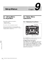
Page 60: ...ay setup menus on the monitor connected to the COMPOSITE OUT 2 SUPER connector HD SDI OUTPUT SUPER connectors or SDI OUT 2 SUPER connector of this unit When a setup menu appears on the monitor a cursor indicates the currently selected menu item 00 26 23 09 001 P ROLL TIME 5 s CHARACTR ON PB EE PB CONFI ENABLE CTL TC TC ASSEMBLE OFF TCG SET HOME LTC DF VITC LTC EXT LTC R RUN REM 00M 0 10 20 30 40 1...

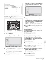
Page 61: ...enu settings to their factory default values proceed as follows 1 Press the MENU button 2 Turn the MULTI CONTROL knob to display setup menu item B20 3 Press the SELECT function button to select the displayed setup menu item B20 4 Turn the MULTI CONTROL knob to set B20 to ON and press the SET function button The current active menu settings are reset to their factory default settings 5 Press the SE...

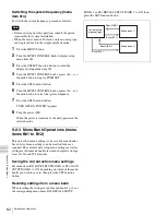
Page 62: ...URN OFF ON POWER appears 8 Turn the power OFF When the power is turned next the unit operates in the selected mode 9 2 3 Menu Bank Operations menu items B01 to B12 This unit allows menu settings to be saved in menu banks Saved sets of menu settings can be recalled for use as required The current active setup menu settings as well as settings saved in menu banks are stored in separate storage areas...

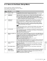
Page 63: ...d to this unit via a 9 pin remote control cable this item determines whether or not to operate the two units in phase synchronization OFF Do not operate in phase synchronization ON Operate in phase synchronization 005 DISPLAY INFORMATION SELECT Determines the kind of character information to be output from the COMPOSITE OUT 2 SUPER connector HD SDI OUTPUT SUPER connectors and SDI OUT 2 SUPER conne...

Page 64: ... 23 98PsF For the procedure for switching the system frequency see Switching the system frequency menu item 013 on page 62 Notes For the basic and extended setup menus separate settings are saved for 59 94i 29 97PsF mode 50i 25PsF mode and 24PsF 23 98PsF mode When you switch systems all menu items change to the settings established in the new system The settings are different from those for the mo...

Page 65: ...3 009 and 011 watch the monitor and adjust to the desired status B12 SAVE SETUP BANK 2 Set to ON to save current active menu settings to menu bank 2 B20 RESET CURRENT SETUP Set to ON to reset current active menu settings to factory default values Item number Item name Settings ...

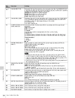
Page 66: ...indicator when the erasure prevention plug on the cassette is pressed in OFF Do not flash the REC INHI indicator ON Flash the REC INHI indicator 108 AUTO EE SELECT When a cassette is inserted and PB EE on the HOME page of the function menu is set to EE select the VTR modes in which input video and audio signals are automatically handled in E E mode S F R In STOP EJECT F FWD REW modes STOP In STOP ...

Page 67: ...nvert mode is displayed in the display window or not OFF Not displayed ON Displayed 144 REW SPEED MAX The tape runs with pinch roller disengaged in rewind mode This setting enables high speed rewinding the tape LIMIT The tape runs with pinch roller engaged in rewind mode This setting enables quick changeover between the rewind mode and the other mode 145 MODE KEY ENABLE DURING RECORDING Set the mo...

Page 68: ... is flashing editing is not executed 309 SERVO AV REFERENCE SEL Select the servo reference signal AUTO1 During recording the input video signal is used as the servo reference signal During playback the signal selected by OUT REF on the P2 VIDEO page of the function menu is used as the servo reference signal If the signal selected by the OUT REF setting is not connected an internal reference signal...

Page 69: ...g cuing up the tape transport is in the pinch ON state maximum tape speed 10 times normal REEL During cuing up the tape transport is in the pinch OFF state As the tape approaches the cue up point and the tape speed drops the tape transport switches to the pinch ON state a To give priority to editing accuracy select CAP Item number Item name Settings 501 STILL TIMER Select the time delay from the t...

Page 70: ... the ID code Display this item in the display window and press the SET function button The ID code setting mode is obtained Select the digit to be set by pressing the T or t function button When you select all digits set the SET function button again The ID code is stored and the ID code setting mode is terminated 604 ID CODE SW Select whether or not to record the ID code set using item 603 in the...

Page 71: ...f timecode signals LTC TCG R Output the playback timecode signal during playback When the edit preset function is on or when recording output the timecode signal generated by the internal timecode generator INPUT Use the same phase as the input video OUTPUT Use the same phase as the output video AUTO Use the same phase as the input video when editing and use the same phase as the output video at o...

Page 72: ...C 3H 0H Set JUMPING TC to STARTING TC 1 frame 630 SEARCH TYPE SELECT ALL Searching for all shot mark in index search operation REC Searching for rec start mark in index search operation SHOT 1 Searching for shot mark 1 in index search operation SHOT 2 Searching for shot mark 2 in index search operation POST Searching for post mark in index search operation STOPc Searching for the stop code in inde...

Page 73: ...recorded The Source Pack Stored Ownership who can be set See Setting Stored Ownership on page 56 Item number Item name Settings Item number Item name Settings 703a BLANK LINE SELECT Switch blanking on or off for individual lines in the vertical blanking interval of the SD video signal The Y C signal and odd even fields are blanked simultaneously Specify the blanking for each line separately BLANK ...

Page 74: ...vel of an SD output signal 0 to 800H to B50H 716a CHROMA GAIN CONTROL Adjust the chroma output level of an SD output signal 0 to 800H to B50H 717a CHROMA PHASE CONTROL Adjust the chroma phase of an SD output signal 0 to 80H to FFH 718a SETUP LEVEL Adjust the SD setup level black level of an SD output signal 0 to 110H to 220H 719a SYSTEM PHASE SYNC Adjust the sync phase of an SD output signal 0 to ...

Page 75: ...inition video signal output from the HD SDI OUTPUT connector according to the menu 0 to 3FFH Item number Item name Settings Note Item number Item name Settings 802 DIGITAL AUDIO MUTING IN SHUTTLE MODE Set the digital audio muting conditions during shuttle playback OFF Not muted CUEUP Muted during cue up or preroll operations FULL Muted in shuttle mode SLOW Muted with the speed less than 0 2 time n...

Page 76: ...hannels to the REC LEVEL adjustment knobs and PB LEVEL adjustment knobs on the front panel CH1 2 Assign the audio channels 1 and 2 CH3 4 Assign the audio channels 3 and 4 1 3 2 4 Assign the audio channels 1 3 and 2 4 REC4 Assign the audio channels 1 to 4 for recording PB4 Assign the audio channels 1 to 4 for playback 832 ANALOG AUDIO INPUT MODE Select the signal recorded on audio channels 3 and 4 ...

Page 77: ...he edge crop mode L BOX Select the letter box mode SQUEZ Select the squeeze mode 931 DOWN CONVERTER LETTER BOX MODE DC Select the aspect ratio of the down converter output when menu item 930 is set to LETTER BOX 16 9 Set the aspect ratio of the HD SD converter output to 16 9 14 9 Set the aspect ratio of the HD SD converter output to 14 9 13 9 Set the aspect ratio of the HD SD converter output to 1...

Page 78: ...r image enhancer the sharpness of edge emphasis 0 to 40H to 7FH 955 LIMITTER UC Adjust the up converter image enhancer the maximum detail level added to emphasize the original signal 0 to 20H to 3FH 956 CRISP THRESHOLD UC Adjust the up converter image enhancer Set the threshold amplitude at which low amplitude signals are not emphasized 0 to 8 to FH 957 LEVEL DEPEND THRESHOLD UC Adjust the up conv...

Page 79: ...technician who has undergone service training For details refer to the Installation Manual 10 2 Head Cleaning To clean the video heads and audio heads always use the special purpose Sony BCT HD12CL cleaning cassette If you insert the cleaning cassette it is automatically ejected after a head cleaning operation which lasts for 10 seconds Follow the instructions with the cleaning cassette carefully ...

Page 80: ...TR ON PB EE PB CONFI DISABLE CTL TC CTL ASSEMBLE OFF TCG SET HOME E14 001 ALARM ERROR 01 REEL TROUBLE 1 Code Message Description 01 REEL TROUBLE Tape slacking has been detected in the threading or unthreading operation 02 REEL TROUBLE Tape slacking or tape breaking has been detected in the SEARCH FF or REW mode 03 REEL TROUBLE Tape slacking tape breaking or supply or take up reel locking has been ...

Page 81: ...the operation of an NV RAM on SV 225 board for the servo system 98 NV RAM ERROR Abnormality has been detected in the operation of an NV RAM on EQ 101 board for the RF system or an NV RAM on DM 123 board for the DM system 99 INTERNAL I F 2 Abnormality in the interface between SYS CPU on SY 320 board and SERVO CPU on SV 225 board or MPU on EQ 101 DM 123 HPR 14 VPR 92 APR 70 and KY 571 board has been...

Page 82: ...ng messages Select a warning message to be cancelled and press the ON OFF function button to display OFF Message Description REFERENCE MISSING No reference signal is input LOST LOCK Capstan servo lock is released during playback recording or editing NO VIDEO INPUT REC No video signal is detected during recording ASYNCHRONOUS VIDEO REC Phase difference of the video input signal and reference signal...

Page 83: ...unit from a cold to a warm location Leave the unit powered off for about 10 minutes in order to give the unit time to detect moisture condensation 10 6 Regular Checks 10 6 1 Digital Hours Meter The digital hours meter can display seven items of information in corresponding display modes about the operational history of the unit Use it as a guide in scheduling periodic maintenance Display modes of ...

Page 84: ... menu item H03 or H13 tape running hours H Mode C See menu item H04 or H14 threading counter times Mode D See menu item H01 operation hours H CHARACTR ON PB EE PB CONFI ENABLE CTL TC TC ASSEMBLE OFF TCG SET HOME LTC DF VITC LTC EXT LTC R RUN REM 00M 0 10 20 30 40 1 CH1 IN CH2 IN OUT MONI L MONI R 60 INPUT ANA 4 HD COND P ROLL D STOP BANK 2 DOLBY NR 4 1 2 SDI ASMBL CONFI ON RECORDER 59 94i EMPH 2 E...

Page 85: ...racteristics of the liquid crystal display such stuck pixels may appear spontaneously These problems have been kept to the absolute minimum but are an unavoidable characteristic of liquid crystal technology Item No Item name Descriptions H01 OPERATION HOURS Total operation hours H H02 DRUM RUNNING HOURS Total drum running hours H H03 TAPE RUNNING HOURS Total tape running hours H H04 THREADING COUN...

Page 86: ... with BCT 40HD 24PsF 23 98PsF Betacam SX playback time 62 minutes with BCT 62SXA Betacam SP playback time 30 minutes with BCT 30MA 525 59 94 36 minutes with BCT 30MA 625 50 Analog Betacam playback time 30 minutes with BCT 30G 525 59 94 36 minutes with BCT 30G 625 50 Rewind time 3 minutes or less with BCT 40HD Fast forward time 4 minutes or less with BCT 40HD Search speed Shuttle mode Still to appr...

Page 87: ...re K factor 2T pulse 1 or less Differential gain 2 or less Differential phase 2 or less Y C delay 20 ns or less Digital Audio CH1 to CH4 Frequency response 20 Hz to 20 kHz 0 5 dB 1 0 dB Standardize at 1 kHz Dynamic range HDCAM 90 dB or more at 1 kHz emphasis on SX 88 dB or more at 1 kHz emphasis on Distortion 0 08 or less at 1 kHz emphasis on reference level 4 dBm Analog Betacam playback Video 525...

Page 88: ...270 Mbits s SMPTE 259 M AUDIO OUTPUT 1 2 XLR 3 pin male 2 4 dBm at 600 Ω load low impedance balanced AUDIO MONITOR OUTPUT L R XLR 3 pin male 2 4 dBm at 600 Ω load low impedance balanced TIME CODE OUT BNC 1 0 Vp p 75 Ω PHONES JM 60 stereo phone jack to 12 dBu at 8 Ω load unbalanced REMOTE 4 pin female AC input 15 V DC max 5 W DC input 10 5 to 17 V DC max 5 W with the optional BVR 3 or RM 280 connec...

Page 89: ...ILURE OF THIS UNIT OR ITS RECORDING MEDIA EXTERNAL STORAGE SYSTEMS OR ANY OTHER MEDIA OR STORAGE SYSTEMS TO RECORD CONTENT OF ANY TYPE Always verify that the unit is operating properly before use SONY WILL NOT BE LIABLE FOR DAMAGES OF ANY KIND INCLUDING BUT NOT LIMITED TO COMPENSATION OR REIMBURSEMENT ON ACCOUNT OF THE LOSS OF PRESENT OR PROSPECTIVE PROFITS DUE TO FAILURE OF THIS UNIT EITHER DURIN...

Page 90: ...080 29 97PsF or 59 94i output is down converted to 480 59 94i c For 576 50i output is up converted to 1080 50i d For 480 59 94i output is up converted to 1080 59 94i Item No Item Name Settings M3 M3A OUTPUT PHASE SELECT M3A0 HD PHASE SEL Select the HD video output signal phase with respect to the reference signal 0H or 90H HD advanced 0H Output in sync with the reference signal 90H Output with the...

Page 91: ...Erasure prevention plug 26 Error message 80 Indication 80 List 80 Extended setup menu 66 F F FWD button 15 Format area 18 Format display 17 Front panel 13 Function button 14 Function menu 31 Basic operations 35 Configuration 31 HOME page 32 Item list 32 P1 PROCS page 32 P2 VIDEO page 33 P3 AUDIO page 33 P4 TC page 33 P5 EDIT page 34 P6 OTHER page 35 H HD SDI INPUT connector 21 HD SDI OUTPUT connec...

Page 92: ...u 60 Setup menus Basic detup menu 63 Configuration 60 Displaying 60 Extended setup menu 66 Menu bank 62 Operations 60 Setting 61 SHIFT button 14 Shot data 51 Displaying 51 Shot mark 51 Cueing up 51 Recording 51 Shuttle mode 44 Stand 24 Replacing 24 Using 24 STANDBY indicator 15 STOP button 15 Stop code 52 Checking the recorded stop code 53 Detecting 52 Erasing 54 Recording 53 Stop code display 17 ...

Page 93: ... for use by the purchasers of the equipment described in this manual Sony Corporation expressly prohibits the duplication of any portion of this manual or the use thereof for any purpose other than the operation or maintenance of the equipment described in this manual without the express written permission of Sony Corporation ...

Page 94: ...Sony Corporation HDW S280 SY 3 857 685 06 1 Printed in Japan 2008 12 13 2004 ...

Reviews: