14
Functional description
Ch
ap
te
r 1 Ov
e
rv
ie
w
Processing
The HDXS-C200 is a high performance server containing
a dual-processor Motherboard, which controls the
operation of the HDDs and other server functions (see
).
Four Dual Inline Memory Modules (DIMMs) are fitted to
the Motherboard to provide 4 GByte of RAM (see
Two of the PCI slots provided by the Motherboard are
fitted with a RAID Controller Card (see
), which controls the Media RAID, and a
NIC Card (see
).
Interface
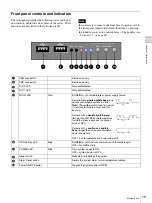
The front panel provides basic controls and status
indicators (see
“Front panel controls and indicators” on
). These are located behind a removable front bezel
which filters the incoming air.
The general status indicators: power, HDD activity and
fault are visible with the bezel in place by means of ‘light
pipes’ fitted to the bezel, which direct the light from these
indictors through the bezel so that they are visible from the
front of the unit with the bezel fitted in place. Additionally
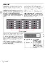
each media RAID HDD provides status LEDs - the bezel
must be removed to see these (see
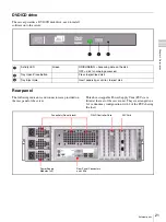
The rear panel provides details status power-on self test
(POST) indicators and connectors (see
connectors and LEDs” on page 23
).
Power distribution
The chassis contains a 2+1 redundant modular power
supply arrangement, ensuring continued operation in the
event of a single PSU failure (see
).
Three independent PSU modules are supplied from
separate a power sources and they equally share the load of
the unit. Green status LEDs are provided on the rear panel
of each module to enable identification of a faulty module.
The three modules are physically located inside a cage and
the outputs are combined to deliver internal dc supplies
directly to the Motherboard which are then routed to the
System Power Board and other internal boards.
Summary of Contents for HDXS-C200
Page 2: ...2 ...
Page 10: ...10 Table of Contents ...
Page 13: ...13 Functional description Chapter 1 Overview ...
Page 68: ...68 PuTTY terminal emulator Chapter 4 Utilities ...
Page 96: ...96 Powered off replacement parts Chapter 6 Parts Replacement ...
Page 101: ...101 Parts location Chapter 8 Spare Parts Parts location 1 2 2 2 2 2 2 2 2 2 2 2 2 ...
Page 102: ...102 Parts location Chapter 8 Spare Parts 101 102 103 104 104 104 104 104 104 104 104 104 ...
Page 104: ...104 Parts location Chapter 8 Spare Parts A B A B 301 302 303 304 305 306 306 306 306 306 ...
Page 105: ...105 ...
Page 106: ...Sony Corporation ...


