24
External parts
Ch
ap
te
r 2 Des
c
rip
tio
n
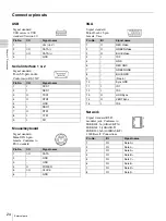
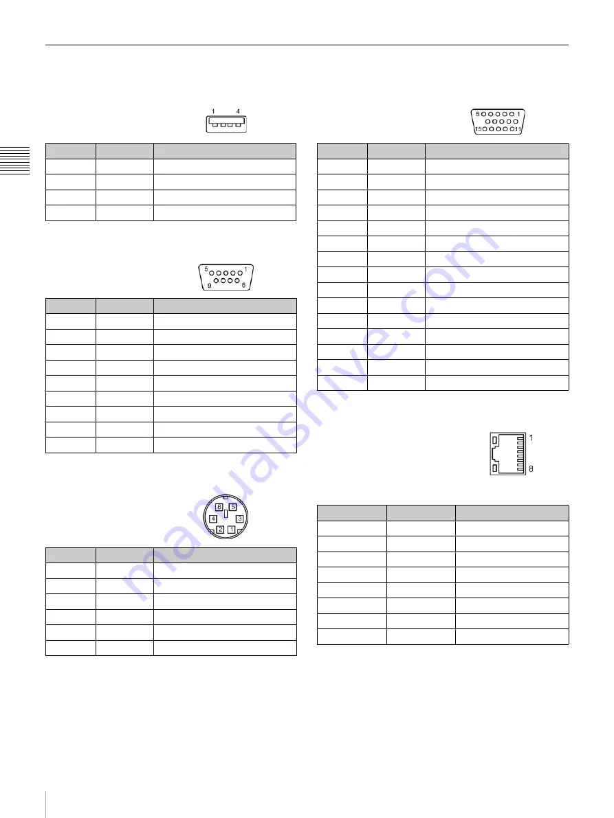
Connector pinouts
USB
Serial interface 1 & 2
Mouse/keyboard
VGA
Network
Signal standard:
USB series A.
USB
standard Version 2.0
Pin No.
I/O
Signal name
1
-
Vcc (+5 V)
2
I/O
DATA (-)
3
I/O
DATA (+)
4
-
GND
Signal standard:
D-sub 9-pin, male.
Conforms to RS-232C
Pin No.
I/O
Signal name
1
I
DCD1
2
I
RXD1
3
O
TXD1
4
O
DTR1
5
-
GND
6
I
DSR1
7
O
RTS1
8
I
CTS1
9
I
RI1
Signal standard:
Mini-DIN 6-pin,
female.
Conforms to
PS/2 standard
Pin No.
I/O
Signal name
1
I/O
DATA
2
-
GND
3
-
GND
4
O
POWER
5
I/O
CLOCK
6
-
GND
Signal standard:
Mini D-sub 15-pin,
female, Vesa
Pin No.
I/O
Signal name
1
O
RED Video
2
O
GREEN Video
3
O
BLUE Video
4
I
ID 2
5
-
GND
6
-
RED GND
7
-
GREEN GND
8
-
BLUE GND
9
-
(No pin)
10
-
Sync GND
11
I
ID 1
12
I
ID 0
13
O
HOR Sync
14
O
VERT Sync
15
I
ID 3
Signal standard: RJ-45
modular jack. Conforms to:
IEEE 802.3u (10BASE-TX)
IEEE 802.3 (10BASE-T)
IEEE 802.3ab (1000BASE-T)
1000 Base-T Connections
Pin No.
I/O
Signal name
1
I/O
Data A+
2
I/O
Data A-
3
I/O
Data A+
4
I/O
Data B+
5
I/O
Data C+
6
I/O
Data B-
7
I/O
Data D+
8
I/O
Data D-
Summary of Contents for HDXS-C200
Page 2: ...2 ...
Page 10: ...10 Table of Contents ...
Page 13: ...13 Functional description Chapter 1 Overview ...
Page 68: ...68 PuTTY terminal emulator Chapter 4 Utilities ...
Page 96: ...96 Powered off replacement parts Chapter 6 Parts Replacement ...
Page 101: ...101 Parts location Chapter 8 Spare Parts Parts location 1 2 2 2 2 2 2 2 2 2 2 2 2 ...
Page 102: ...102 Parts location Chapter 8 Spare Parts 101 102 103 104 104 104 104 104 104 104 104 104 ...
Page 104: ...104 Parts location Chapter 8 Spare Parts A B A B 301 302 303 304 305 306 306 306 306 306 ...
Page 105: ...105 ...
Page 106: ...Sony Corporation ...


