

Overview
The HFBK-HD1 is an optional board designed to be
installed in the following apparatuses:
• HFU-X310 HD Camera Interface Unit
• BRC-H700 HD 3CCD Color Video Camera
• BRU-H700 HD Optical Multiplex Unit
The board supplies images from the color video camera
connected to the apparatus that accommodates the board
as HD SDI signals. It also has a 15-pin connector for
analog output (Y/Pb/Pr or RGB).
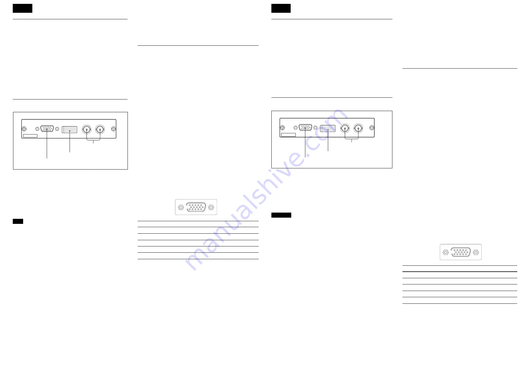
Locations and Functions of Parts
1
MONITOR connector (D-sub 15-pin)
For analog video output. The configuration of the output
signal can be specified by setting the DIP switches.
2
DIP switches
To configure the type of output from the MONITOR
connector.
Note
Turn the apparatus that accommodates the board off
before changing the DIP switch settings.
Switch 1 (VD/Sync)
Selects the signal to be supplied from pin 14 of the
MONITOR connector:
Upper (Sync): To output composite sync (3-level sync)
(factory setting)
Lower (VD): To output vertical sync
Switch 2 (Sync)
Specifies whether to add a sync signal to each of the R, G,
and B signals when the RGB output is selected:
Upper (Add Sync): To output each of the R, G, and B
signals with a sync signal (factory setting)
Lower (No Sync): Not to add any sync
Switch 3 (RGB/YPbPr)
Selects the type of component output from the
MONITOR connector:
Upper (YPbPr): To output component signals (factory
setting)
Lower (RGB): To output RGB signals
3
HD-SDI connectors (BNC type)
For digital video output. The two connectors output the same
signal.
Specifications
General
Power requirements
+12 V DC, 400 mA (supplied from the
apparatus that accommodates the board)
Operating temperature
5
°
C to 40
°
C (41
°
F to 104
°
F)
Storage temperature
–20
°
C to +60
°
C (–4
°
F to +140
°
F)
Storage humidity 20% to 90% (relative, no condensation)
Dimensions
134
×
26.2
×
112.8 mm (w/h/d)
(5
3
/
8
×
1
1
/
16
×
4
1
/
2
inches)
not including projecting parts
Mass
Approx. 0.16 kg (6 oz)
Outputs
HD-SDI
BNC type (2)
Conforms to SMPTE292M, 75
Ω
MONITOR
D-sub 15-pin (1)
Output level
Component:
Y: 1.0 Vp-p
Pb, Pr: 0.7 Vp-p, 75
Ω
R/G/B: 1.0 Vp-p, 75
Ω
HD/VD: TTL level
Sync: 0.6 Vp-p, 75
Ω
(3-level sync)
Pin assignment
Pin
Signal
Pin
Signal
Pin
Signal
1
R/Pr (X)
6
R/Pr (G)
11
NC
2
G/Y (X)
7
G/Y (G)
12
NC
3
B/Pb (X)
8
B/Pb (G)
13
HD
4
NC
9
NC
14
VD/SYNC
5
GND
10
GND
15
NC
Supplied accessory
Operation Manual (1)
Design and specifications are subject to change without
notice.
5
1
6
10
15
11
Description générale
La HFBK-HD1 est une carte en option conçue pour être
installée dans les appareils suivants :
• Interface caméra HD HFU-X310
• Camera vidéo couleur HD 3CCD BRC-H700
• Module multiplex optique HD BRU-H700
La carte fournit des images provenant d’une caméra vidéo
couleur connectée à l’appareil qui contient la carte comme
signaux HD SDI. Elle comporte aussi un connecteur à 15
broches pour une sortie analogique (Y/Pb/Pr ou RVB).
Emplacement et fonction des pièces
1
Connecteur MONITOR (D-sub 15 broches)
Pour une sortie vidéo analogique. La configuration du signal
de sortie peut être spécifiée en réglant les commutateurs DIP.
2
Commutateurs DIP
Pour configurer le type de sortie du connecteur MONITOR.
Remarque
Mettez l’appareil contenant la carte hors tension avant de
changer les réglages des commutateurs DIP.
Commutateur 1 (VD/Synchro)
Permet de sélectionner le signal fourni par la broche 14 du
connecteur MONITOR.
Position supérieure (Synchro) : Sortie d’un signal de
synchro composite (synchro 3 niveaux) (réglage d’usine)
Position inférieure (VD) : Sortie d’un signal de synchro
verticale
Commutateur 2 (Synchro)
Permet de spécifier si un signal de synchro sera ajouté à
chacun des signaux R, V et B lorsque la sortie RVB est
sélectionnée.
Position supérieure (Ajout de synchro) : Sortie de chacun
des signaux R, V et B avec un signal de synchro (réglage
d’usine)
Position inférieure (Pas de synchro) : Pas d’ajout de signal
de synchro
Commutateur 3 (RVB/YPbPr)
Permet de sélectionner le type de signaux composantes sortis
par le connecteur MONITOR.
Position supérieure (YPbPr) : Sortie de signaux
composantes (réglage d’usine)
Position inférieure (RVB) : Sortie de signaux RVB
3
Connecteurs HD-SDI (type BNC)
Pour une sortie vidéo numérique. Les deux connecteurs
sortent le même signal.
Spécifications
Généralités
Alimentation
+12 V CC, 400 mA (fourni par
l’appareil contenant la carte)
Température de fonctionnement
5 °C à 40 °C (41 °F à 104 °F)
Température de rangement
–20 °C à +60 °C (–4 °F à +140 °F)
Humidité de rangement
20 % à 90 % (relatif, sans
condensation)
Dimensions
134
×
26,2
×
112,8 mm (l/h/p)
(5
3
/
8
×
1
1
/
16
×
4
1
/
2
pouces)
pièces saillantes non comprises
Poids
Environ 0,16 kg (6 oz)
Sorties
HD-SDI
Type BNC (2)
Conforme à SMPTE292M, 75
Ω
MONITOR
D-sub 15 broches (1)
Niveau de sortie
Composantes :
Y : 1,0 Vc-c
Pb, Pr : 0,7 Vc-c, 75
Ω
R/V/B : 1,0 Vc-c, 75
Ω
HD/VD : Niveau TTL
Synchro : 0,6 Vc-c, 75
Ω
(synchro 3
niveaux)
Affectation des broches
Broche Signal
Broche Signal
Broche Signal
1
R/Pr (X)
6
R/Pr (G)
11
NC
2
V/Y (X)
7
V/Y (G)
12
NC
3
B/Pb (X)
8
B/Pb (G)
13
HD
4
NC
9
NC
14
VD/SYNC
5
GND
10
GND
15
NC
Accessoires fournis
Mode d’emploi (1)
La conception et les spécifications sont susceptibles d’être
modifiées sans préavis.
3
Connecteurs HD-SDI
2
Commutateurs DIP (derrière le cache)
1
Connecteur MONITOR
HFBK-HD1
MONITOR
HD-SDI
HD-SDI
5
1
6
10
15
11
3
HD-SDI connectors
2
DIP switches (behind the cover)
1
MONITOR connector
HFBK-HD1
MONITOR
HD-SDI
HD-SDI
English
Français


