PFV-SP3100
1-4 (E)
1-5. Installing Optional Board
1-5. Installing Optional Board
The optional board can be installed in any empty slot of
PFV-SP3100.
When installing the processing module controller, the No.4
slot is used as the master slot and the No.3 slot is used as
the sub-slot.
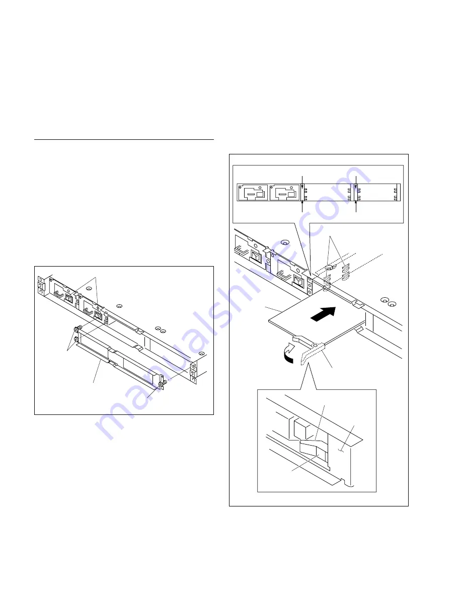
Installing Main Board (Front side)
Two slots are used depending on the optional board.
In this section, the illustrations for the single-slot type’s
board are described.
1.
Turn off the power switches of PFV-SP3100.
n
Turn off both of the power switches when the backup
power supply unit is installed.
2.
Remove the front panel. (Refer to Section 1-4.)
3.
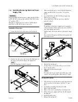
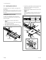
Loosen the four screws and remove the board retainer.
B 3
x
8
(with stopper)
Board retainer
Power switches
B 3
x
8
(with stopper)
4
3
2
1
1
Board lever
Slot label
Board retainer
Board lever
Board guides
Main board
Slot 4
Slot 3
Slot 2
Slot 1
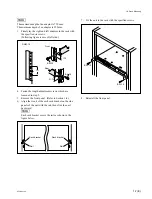
4.
Insert the main board fully into the slot along the board
guides and close the board lever in the direction
indicated by arrow
1
.
5.
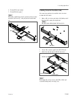
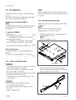
Stick the slot label supplied with the PFV-SP3100 onto
the board lever.
n
Attach the supplied slot label to the position where it is
not concealed by the board retainer as shown in the
figure.


