HT-CT800
7
INITIALIZING METHOD
It can return all settings to the initial state of factory shipment.
Note 1:
Disconnect the following connections when using this mode.
USB
LAN
HDMI IN 1
HDMI IN 2
HDMI IN 3
Note 2:
The operation in this mode must use the remote commander and
TV monitor.
Procedure:
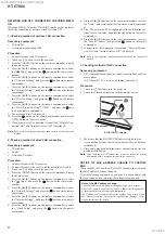
1. Connect this unit with TV monitor.
2. Touch the [
1
] button to turn the power on
3. Press the [HOME] button on the remote commander, and the
home menu is displayed.
4. Press the [
V
]/[
v
] buttons on the remote commander to select
the “ Setup”, and press the [ ] button on the remote com-
mander.
5. Press the [
V
]/[
v
] buttons on the remote commander to select
the “Resetting”, and press the [ ] button on the remote com-
mander.
6. Select “Reset to Factory Default Settings”, and press the [ ]
button on the remote commander.
7. Press the [
V
]/[
v
] buttons on the remote commander to select
the “All Settings”, and press the [ ] button on the remote com-
mander.
8. Press the [
B
]/[
b
] buttons on the remote commander to select
the “Start”, and press the [ ] button on the remote commander.
9. Turn the power off automatically, and initialization ends.
Note 3:
By perform resetting, the link with the subwoofer may be lost. In
this case, refer to “WIRELESS CONNECTION (LINK) WORK
OF BAR SPEAKER AND SUBWOOFER” on this page.
NOTE OF REPLACING THE NFC BOARD FOR RE-
PAIRING
When the NFC board is defective, replace the complete mounted
board.
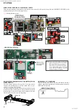
The mounted parts cannot be replaced with single for repairing.
NOTE OF REPAIRING THE MB-1612 BOARD
Among mounted parts on the MB-1612 board, only parts that are
described in the electrical parts list can be replaced for repair.
When the parts that are not described in the electrical parts list are
defective, replace the complete mounted board.
In this service manual, the schematic diagram of the MB-1612
board is not described.
NOTE OF REPLACING THE ELECTRICAL PARTS ON
EACH BOARDS FOR REPAIRING
Among mounted electrical parts on each boards, only parts that
are described in the electrical parts list can be replaced for repair.
The parts that are not described in the electrical parts list cannot be
replaced with single for repairing.
WIRELESS CONNECTION (LINK) WORK OF BAR SPEAK-
ER AND SUBWOOFER
When the parts below is replaced, the wireless connection (LINK)
of the Bar speaker and Subwoofer will be disconnected.
Before returning repaired products to the customer, follow the pro-
cedure below to LINK the Bar speaker and Subwoofer.
Also, if only the Bar speaker or Subwoofer is brought in for repair
and the parts below are replaced, be sure to inform the customer
when returning the repaired products that the customer must LINK
the Bar speaker and Subwoofer.
(Indicate that the LINK procedure is described in the operating
instructions)
Parts in which the LINK will be disconnected due to re-
placement:
• MB-1612
board
• RF modulator (SWA12-4V TX)
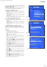
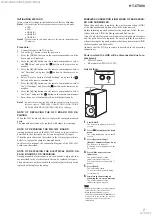
Link method:
1
Press HOME.
The home menu appears on the TV
screen.
2
Select
[Setup] from the home
menu.
The setup display appears on the TV
screen.
3
Select [System Settings] -
[Wireless Subwoofer Connection].
The [Wireless Subwoofer
Connection] screen appears on the
TV screen.
LINK
Power indicator
4
Press LINK on the rear of the
subwoofer.
The power indicator of the
subwoofer flashes in green.
Proceed to the next step within 1
minute.
5
Select [Start].
The link setting starts.
To return to the previous display,
select [Cancel].
6
Complete the link setting by
following the on-screen message.
The power indicator of the
subwoofer lights in green.
• If the message [Cannot set Link.] appears,
follow the on-screen instructions.
• When [Bluetooth Mode] is set to
[Transmitter] and the BLUETOOTH device
is connected to the system, the wireless
subwoofer connection cannot be
established.
Notes
SYS SET
2019/09/24 22:06:08 (GMT+09:00)


