HT-GT1
7
Note:
Follow the disassembly procedure in the numerical order given.
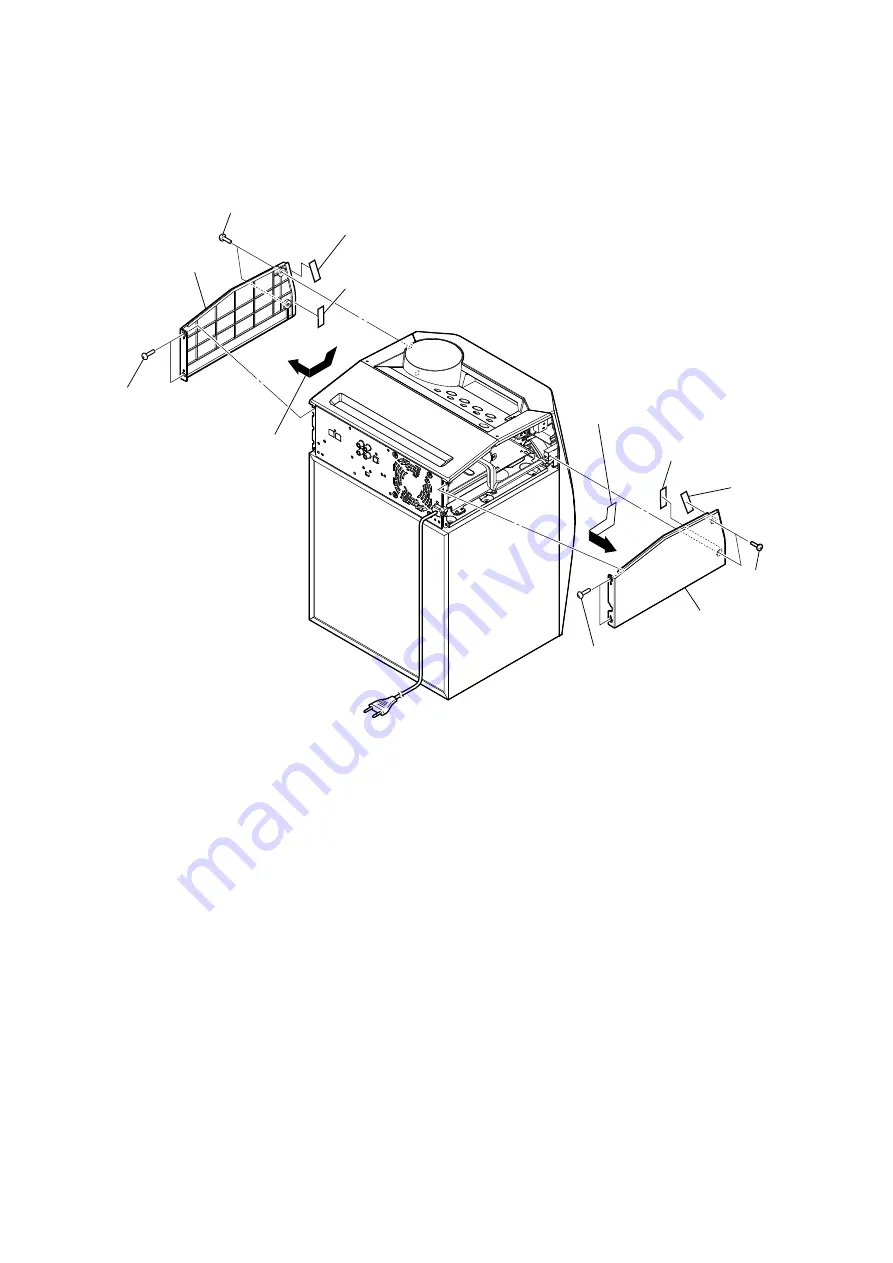
2-2. SIDE L, R PANEL
1
two tapping
screws
(HEX)
2
two screws
(BVTP3
u
10)
1
two tapping
screws
(HEX)
2
two screws
(BVTP3
u
10)
3
Remove the side L panel block
in the direction of the arrow.
6
side L panel
3
Remove the side R panel block
in the direction of the arrow.
6
side R panel
4
saranet cushion
(10T25)
4
saranet cushion
(10T25)
4
saranet cushion
(10T25)
5
saranet cushion
(7T25)
– Rear view –


