background image

Help Guide

Flash

HVL-F28RM

List of flash settings

While this flash unit is attached to a camera with external flash setting capabilities, you can change the following flash settings:

External flash firing settings

Note

The items and options available for setting vary depending on the flash mode.

Performing the reset operation on this flash unit resets the all of the above external flash firing settings to the factory defaults. For the reset

operation, see “

Resetting the flash firing settings to the factory defaults

.”

External flash custom settings

Setting

items

Descriptions

Setting options

Flash

Control

Mode

Flash control mode setting

TTL Flash Firing (*)/Manual Flash Firing/Multi Flash

Firing/Group Flash Firing

Memory

recall

Calling up the registered preferences

Off (*)/MR1/MR2

High Speed

Sync

High-speed sync setting

On (*)/Off

CMD Flash

Firing

Flash firing setting of this flash unit that is configured

as the commander unit

On (*)/Off

Flash Comp. Flash compensation setting

3.0 - 

3.0 (*: ±0.0)

Flash Power

Level

Flash power level setting

1/1 (*) - 1/128, Off

Flash

Interval

Intervals for firing flashes in multi flash firing mode

1Hz - 100Hz (*: 5Hz)

Number of

Flashes

Number of flashes to fire in multi flash firing mode

2 - 100 (*: 10), Continuous

Ratio Control Flash power ratio control setting

On/Off (*)

Ratio Value

(A)

Ratio Value

(B)

Ratio Value

(C)

Flash power ratio settings

OFF/1 (*) - 16

Factory default

*

Setting items

Descriptions

Setting options

Memory

Registers the current mode or settings.

-

39

Summary of Contents for HVL-F28RM

Page 1: ...era models compatible with the flash unit view here Another window will open Locating parts and controls Preparations Unpacking Inserting batteries Attaching removing the flash unit to from the camera Attaching removing the mini stand Removing attaching the dust and moisture resistant cover Turning on the power to the flash unit Pairing with a radio wireless commander receiver for radio wireless f...

Page 2: ...ering calling up a preference Viewing the version information of this flash unit the receiver unit List of flash settings Tips for the customers using a camera without external flash setting capabilities Resetting the flash firing settings to the factory defaults Restoring the factory default state of the flash unit Notes on using cleaning the flash unit Notes on use Specifications Specifications ...

Page 3: ... photography use the built in wide panel To use the built in wide panel gently pull out the wide panel along with the bounce sheet from the front of this flash unit and fold down the wide panel to cover the flashlamp Push the bounce sheet back into the flash unit Flash unit back side Built in wide panel 1 Flashlamp 2 Bounce sheet 3 Micro USB terminal 4 Multi Interface foot 5 3 ...

Page 4: ...le 2 Lock lever 3 Release button 4 Bounce lock release button 5 Battery chamber door 6 Dust and moisture resistant cover 7 CMD lamp 1 LEVEL lamp 2 LEVEL button 3 TEST button 4 LINK lamp 5 PAIRING button 6 Power switch 7 Shoe for the Multi Interface foot 1 Tripod attachment hole 2 4 ...

Page 5: ...5 023 112 11 1 Copyright 2020 Sony Corporation 5 ...

Page 6: ...lease contact your dealer The number in the parentheses indicates the quantity Flash unit 1 Connector protect cap attached 1 Dust and moisture resistant cover attached 1 Mini stand 1 Pouch 1 Set of printed documentation 5 023 112 11 1 Copyright 2020 Sony Corporation 6 ...

Page 7: ...e batteries with the specified battery charger Do not use lithium ion batteries in this flash unit as they may prevent the flash unit from delivering full performance 5 023 112 11 1 Copyright 2020 Sony Corporation Slide open the battery chamber door following the steps indicated in the following illustration 1 Insert the batteries into the battery chamber as illustrated indicate the direction of t...

Page 8: ...otect cap to the Multi Interface foot to protect its terminal Turn the power switch on the flash unit to OFF 1 Press and hold the release button and rotate the lock lever away from LOCK 2 Remove the connector protect cap from the flash unit and the shoe cap from the camera If the built in flash on the camera is popped up put it down 3 Insert the Multi Interface foot of the flash unit into the Mult...

Page 9: ...5 023 112 11 1 Copyright 2020 Sony Corporation 9 ...

Page 10: ...rew the mini stand to a tripod through the screw hole on the mini stand Use a tripod with the screw that is shorter than 5 5 mm 7 32 in in length To a tripod with the longer screw you cannot secure the mini stand firmly with the screw resulting in possible damage to the mini stand Press and hold the release button and rotate the lock lever away from LOCK 1 Remove the connector protect cap from the...

Page 11: ...Note When you are finished with using this flash unit be sure to attach the connector protect cap back to the Multi Interface foot 5 023 112 11 1 Copyright 2020 Sony Corporation 11 ...

Page 12: ...you attach the cover properly to the flash unit by following these steps To remove the dust and moisture resistant cover Push down a corner of the dust and moisture resistant cover to take it off of the Multi Interface foot To attach the dust and moisture resistant cover Press and hold the release button and rotate the lock lever away from LOCK 1 Orient the dust and moisture resistant cover with r...

Page 13: ...at the dust and moisture resistant cover is not distorted and there is no gap between the cover and the flash unit Tug each of the four corners of the cover to make sure it is firmly in place If the attached cover is distorted remove and attach it back on 4 13 ...

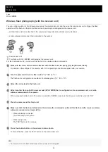
Page 14: ...t is removed from a camera or is attached to the camera in a power saving state the power to the flash unit will be automatically turned off to conserve the battery power During wireless flash photography with the flash unit being used as an off camera flash unit the flash unit goes into power saving mode in 60 minutes Turn the power switch on this flash unit to ON The flash unit is powered To con...

Page 15: ...of firing flashes in this state When flashing quickly The flash unit is not capable of firing flashes Replace the batteries Notes on continuous flash firing If this flash unit fires flashes in quick succession for a short period of time its built in safety circuit will be triggered to suspend flash firing and the flash interval may be forced to extend In addition if the temperature inside the flas...

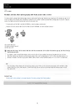
Page 16: ...as the commander unit and the other as the receiver unit To configure this flash unit as the commander unit turn its power switch to ON To configure this flash unit as the receiver unit turn its power switch to A B or C 1 Press and hold the PAIRING buttons on this flash unit and the other device for 3 seconds The LINK lamps on the commander and receiver units flash in green On the commander unit t...

Page 17: ...ed device You can view or delete the paired receiver unit s by selecting External Flash Set Ext Flash Cust Set Disp Paired Devices from the menu of the camera attached with this flash unit For details refer to the operating instructions supplied with your camera Note To switch the roles of the commander and receiver units for radio wireless flash photography repeat the pairing procedure all over a...

Page 18: ...t to specify TTL Flash Firing for the flash control mode For details on the external flash settings of the camera refer to the operating instructions supplied with your camera By default TTL Flash Firing is specified for the flash control mode For camera models compatible with this flash unit visit the website at https www sony net dics f28rm 1 Press the shutter button on the camera to take a phot...

Page 19: ...TEST button is lit When flash compensation is made both on this flash unit and the camera both compensation values are added up for flash firing When a wide angle lens with the focal length of less than 24 mm is used the periphery of the monitor screen on the camera may appear darker When a physically long lens is used the flash light may be obstructed by the lens end 5 023 112 11 1 Copyright 2020...

Page 20: ...photography group flash photography an appropriate flash power level may not be retained In manual flash firing mode the flash power level measured during TTL flash photography is retained If you change the settings that affect the flash power level such as the flash power level setting after photographing the changed settings will not be retained When you have made such changes perform TTL flash ...

Page 21: ...han 24 mm is used the periphery of the monitor screen on the camera may appear darker When a physically long lens is used the flash light may be obstructed by the lens end Related Topic TTL flash photography TTL 5 023 112 11 1 Copyright 2020 Sony Corporation 21 ...

Page 22: ...ync speed This restriction does not apply to cameras designed for high speed sync photography since they allow flash photography at the maximum shutter speed of the camera Note If you set the shutter speed of the camera faster than 1 4000 and take a photo bright and dark streaks may appear on the photo It is recommended that you set the flash power level in manual flash firing mode to at least 1 2...

Page 23: ...ith this flash unit to specify Multi Flash Firing for the flash control mode For details on the external flash settings of the camera refer to the operating instructions supplied with your camera 1 Operate the camera to specify the flash interval the number of flashes and the flash power level for multiple flash photography 2 Operate the camera to specify the shutter speed and the aperture The shu...

Page 24: ...ash power levels Flash intervals Hz 100 90 80 70 60 50 40 30 20 10 9 8 7 6 5 4 3 2 1 1 32 10 10 10 10 10 10 15 15 15 15 15 15 15 15 15 20 25 50 100 1 64 25 25 25 25 25 25 25 25 25 35 40 40 50 65 90 100 100 100 100 1 128 50 50 50 50 60 60 60 65 95 100 100 100 100 100 100 100 100 100 100 Flash power levels Flash intervals Hz 100 90 80 70 60 50 40 30 20 10 9 8 7 6 5 4 3 2 1 1 8 5 5 5 5 5 5 5 5 5 5 6 ...

Page 25: ...ernal Flash Set Ext Flash Firing Set Test Flash from the menu of the camera attached with this flash unit and then change the setting option When 1 Time or Group is specified for firing test flashes in multi flash firing mode this flash unit fires the specified number of test flashes of the specified flash power level at the specified flash intervals while you press and hold the TEST button During...

Page 26: ...ceiver unit Hint The radio wireless communication distance available between the commander unit and the receiver unit is approximately 35 m 114 ft Acquired under our measurement conditions Select External Flash Set Ext Flash Cust Set Commn Channel from the menu of the camera attached with this flash unit and then specify the channel to use for radio wireless communications By default Auto is speci...

Page 27: ...Related Topic Pairing with a radio wireless commander receiver for radio wireless flash photography 5 023 112 11 1 Copyright 2020 Sony Corporation 27 ...

Page 28: ...n for Wireless Flash For details on the settings of the camera refer to the operating instructions supplied with your camera 1 Turn the power switch on the flash unit to A B or C The flash unit is configured as a member of a wireless group A B or C 2 Attach the mini stand to the flash unit 3 Attach another flash unit of the same model HVL F28RM that is configured as the commander unit or a radio w...

Page 29: ...r level of the receiver unit by pressing the LEVEL button on the commander unit Related Topic Pairing with a radio wireless commander receiver for radio wireless flash photography Attaching removing the mini stand 5 023 112 11 1 Copyright 2020 Sony Corporation 29 ...

Page 30: ...member of the wireless group A When you do not want the commander unit to fire flashes select External Flash Set Ext Flash Firing Set CMD Flash Firing from the menu of the camera attached with the commander unit and then specify Off Related Topic Pairing with a radio wireless commander receiver for radio wireless flash photography 5 023 112 11 1 Copyright 2020 Sony Corporation Work with the menu o...

Page 31: ...ower level measured during TTL flash photography is automatically applied to the flash power level for each of the wireless groups A B and C during manual flash photography The commander unit fires flashes as a member of the wireless group A When you do not want the commander unit to fire flashes select External Flash Set Ext Flash Firing Set CMD Flash Firing from the menu of the camera attached w...

Page 32: ...etting or the zoom setting of the receiver unit Note When the value specified for the zoom setting on the commander unit is larger or smaller than the zoom setting values available on the receiver unit its maximum or minimum value is specified for the zoom setting on the receiver unit 5 023 112 11 1 Copyright 2020 Sony Corporation Work with the menu of the camera attached with the commander unit t...

Page 33: ...lash HVL F28RM Notes on wireless flash photography During photography with off camera flash units P TTL flash metering is automatically used instead of ADI metering 5 023 112 11 1 Copyright 2020 Sony Corporation 33 ...

Page 34: ...e shadows and producing a softer light on the screen A Bounce flash photography B Standard flash photography About bounce lock mechanism When the flashlamp is tilted to the 0 degree 0 position the flashlamp is locked bounce lock mechanism to disable adjustment of the bounce flash angle To adjust the bounce flash angle when the flashlamp is locked press and hold the bounce lock release button and t...

Page 35: ...a white ceiling or wall to bounce the flash light A colored surface may tint the bounced light High ceilings or glass are not recommended for the bounce surface 5 023 112 11 1 Copyright 2020 Sony Corporation 35 ...

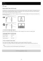
Page 36: ...era to the subject the focal length of the lens To bounce the flash light upward Determine the bounce flash angle with consideration for the focal lengths of the lens listed in the following table Tips on using the bounce sheet The bounce sheet creates a highlight in the subject s eyes and makes the subject look more vibrant The bounce sheet is pulled out along with the wide panel from this flash ...

Page 37: ...hen register the setup all over again by selecting External Flash Set Ext Flash Cust Set Memory from the menu of the camera attached with this flash unit When you do not intend to use the registered preferences select Off in the procedure for calling up the registered preferences 5 023 112 11 1 Copyright 2020 Sony Corporation Set up this flash unit as you want for registering as a preference 1 Wor...

Page 38: ... 11 1 Copyright 2020 Sony Corporation Work with the menu of the camera attached with this flash unit to select the device of your choice When a receiver unit is selected the contents of the displayed information vary depending on the radio conditions When no receiver units are paired no receiver units are available for selection For details on the external flash settings of the camera refer to the...

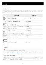
Page 39: ...de setting TTL Flash Firing Manual Flash Firing Multi Flash Firing Group Flash Firing Memory recall Calling up the registered preferences Off MR1 MR2 High Speed Sync High speed sync setting On Off CMD Flash Firing Flash firing setting of this flash unit that is configured as the commander unit On Off Flash Comp Flash compensation setting 3 0 3 0 0 0 Flash Power Level Flash power level setting 1 1 ...

Page 40: ...ep setting 0 3EV 0 5EV Receiver Set Changes the settings of individual paired receiver units Commn Channel Wireless channel setting Auto CH1 CH14 Disp Paired Devices Displays the information about the paired devices Power Save Power saving timer setting 30 Sec 3 Min 30 Min Off WL Power Save Power saving timer setting during wireless flash photography 60 Min 240 Min Off Version Displays the version...

Page 41: ...h unit Note It is recommended that you reset the flash firing settings to the factory defaults before performing TTL flash photography The settings of this flash unit are retained when it is attached to a camera without external flash setting capabilities as well While this flash unit is removed from a camera you cannot view the firmware version Related Topic TTL flash photography TTL Firing test ...

Page 42: ...ng settings see List of flash settings Note While the reset process is in progress do not turn off the power to the flash unit or remove its batteries 5 023 112 11 1 Copyright 2020 Sony Corporation Make sure that this flash unit is powered and then press and hold the LEVEL button and the LEVEL button simultaneously for 3 seconds The TEST button and the LINK lamp light in red and then the flash fir...

Page 43: ...lash unit For the setting items and options available for the flash firing settings see List of flash settings Note While the initialize process is in progress do not turn off the power to the flash unit or remove its batteries 5 023 112 11 1 Copyright 2020 Sony Corporation Make sure that this flash unit is powered and then press and hold the LEVEL button and the PAIRING button simultaneously for ...

Page 44: ...ly stop operating shortly or immediately after the TEST button starts flashing in orange Do not use lithium ion batteries in this flash unit as they may prevent the flash unit from delivering full performance Depending on the time elapsed since manufacture of the batteries the flash interval and the number of flashes may vary from the values shown in the Specifications table even when this flash u...

Page 45: ...dents Place this flash unit on a stable place Placing the flash unit on a wobbling table or a tilted surface may cause the flash unit to fall off resulting in injuries Before attaching this flash unit to a camera make sure that the flash unit is not powered Attaching the powered flash unit to a camera may cause malfunctions or unexpected flashes resulting in eye damage by strong light Maintenance ...

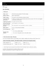
Page 46: ...chargeable nickel metal hydride batteries Operating temperature 0 C to 40 C 32 F to 104 F Storage temperature 20 C to 60 C 4 F to 140 F Dimension w h d Approx 65 1 mm 83 5 mm 91 4 mm 2 5 8 in 3 3 8 in 3 5 8 in Mass Approx 219 g 7 8 oz excluding the batteries Power requirements DC 3 V Recommended batteries Two AA size alkaline batteries Two AA size rechargeable nickel metal hydride batteries Flash ...

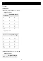
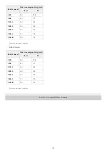
Page 47: ...h power level Flash coverage setting mm 24 50 1 1 20 28 1 2 14 1 19 8 1 4 10 14 1 8 7 1 9 9 1 16 5 7 1 32 3 5 4 9 1 64 2 5 3 5 1 128 1 8 2 5 When the wide panel is attached Flash power level Flash coverage setting mm 24 50 1 1 20 28 1 2 14 1 19 8 1 4 10 14 1 8 7 1 9 9 1 16 5 7 1 32 3 5 4 9 1 64 2 5 3 5 1 128 1 8 2 5 When the wide panel is attached Shutter speed Flash coverage setting mm 24 50 47 ...

Page 48: ... 4 10 8 1 500 4 6 7 7 1 1000 3 2 5 4 1 2000 2 3 3 8 1 4000 1 6 2 7 1 8000 1 1 1 9 1 16000 0 8 1 4 When the wide panel is attached Shutter speed Flash coverage setting mm 24 50 1 250 6 4 10 8 1 500 4 6 7 7 1 1000 3 2 5 4 1 2000 2 3 3 8 1 4000 1 6 2 7 1 8000 1 1 1 9 1 16000 0 8 1 4 When the wide panel is attached 48 ...

Page 49: ...cy band 2 4 GHz Number of channels 14 channels Communication distance Approximately 35 m 114 ft Acquired under our measurement conditions The distance given above applies under conditions where there are no obstacles shielding or radio wave interferences The communication distance may be shorter depending on the positioning of the products the ambient environment and weather conditions 49 ...

Page 50: ...Help Guide Flash HVL F28RM Trademarks Multi Interface Shoe is a trademark of Sony Corporation 5 023 112 11 1 Copyright 2020 Sony Corporation 50 ...

Reviews: