19
Names and Functions of Parts
Chapt
er 1 Ov
erv
ie
w
Using this unit for medical purposes
This equipment’s connectors are not isolated.
Do not connect any device other than one which conforms
to IEC60601-1.
When an information technology device or AV device that
uses an alternating current is connected, current leakage
may result in an electric shock to the patient or operator.
If use of such a device is unavoidable, isolate its power
supply by connecting an isolation transformer, or by
connecting an isolator between the connecting cables.
After implementing these measures, confirm that the
reduced risk now conforms to IEC60601-1.
Do not come into contact with the terminals of the rear
panel connectors and patients at the same time.
Doing so may result in a generation of voltage that can be
harmful to patients if the unit is malfunctioning.
Always disconnect the power cord before connecting and
disconnecting connectors.
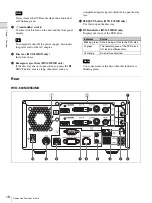
a
AUDIO (analog audio signal) input connector
(stereo mini jack)
Inputs analog audio signals.
b
AUDIO (analog audio signal) output connector
(stereo mini jack)
Outputs analog audio signals.
c
Network connector (RJ-45)
Connect a 1000 Base-T or 100 Base-TX network
cable here.
• For safety, do not connect the connector for
peripheral device wiring that might have excessive
voltage to this port. Follow the instructions for this
port.
• When you connect the LAN cable of the unit to
peripheral device, use a shielded-type cable to
prevent malfunction due to radiation noise.
d
USB 2 and 3 ports
Connect USB devices here.
Supported USB devices
• Use Sony USB media formatted in the FAT32 file
system.
• The connectors do not support all USB devices.
• USB hubs and devices with built-in hubs are not
supported.
Using this unit for medical purposes
The connectors on this unit are not isolated.
Always use USB-compatible external hard drives and
USB memory devices that operate solely on the power
supplied by the unit.
Connecting a device that operates on an AC power
supply may result in an influx of leakage currents from
the connected device, which may in turn result in
electric shocks to the patient and operator.
If use of such devices cannot be avoided, be sure to
connect an isolation transformer to the power supply
of the connected device or connect an isolator between
the connection cables to isolate the power supply, and
verify that the risk of electric shock from the system
has been sufficiently reduced to levels that conform to
IEC60601-1 standards.
e
REMOTE contact switch connectors 1 to 2
(stereo mini jack)
Use these to control the unit via contact switches.
For details on contact switches, see “[Contact Switch]
Tab” (page 79).
f
REMOTE MONITOR connector (RJ-45)
Use this to perform monitor controls.
For details on monitor controls, see “[Contact
Switch] Tab” (page 79).
g
REMOTE RS-232C connector (9-pin D-sub)
Use this connector when controlling this unit or
external devices from a serial interface device.
h
USB 4 port
Connect USB devices here. The same controls that can
be performed on an RS-232C device can be performed
on a connected USB device.
i
DC IN connector
Connect the DC power cable of the supplied AC
adapter here.
Connecting the DC connector to the unit before
connecting the AC power cord from the AC adapter.
Conversely, disconnect the AC power cord from the
AC adapter before disconnecting the DC connector.
Do not touch the patient while touching the pins the
DC connector. The 24 V voltage applied to the pins of
the DC connector may adversely the patient.
j
Equipotential grounding terminal
Use this for equipotential grounding connections.
Caution
Tip
Warning
Caution
Warning
Caution
Summary of Contents for HVO-500MD
Page 106: ......


