80
Menu Contents
Chapt
er
7
Men
u
s
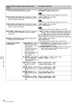
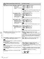
TC SELECT [> TC select]:
Determine which to display in the
time counter display, TC or VITC.
Note
TC is always displayed regardless of the setting of this menu
item during the HDV mode.
VITC [>> VITC]:
Display VITC.
*
TC [>> TC]:
Display TC.
VITC [> VITC]:
Determine whether to record the internally
generated timecode as VITC.
Note
The setting of this menu item has no effect during HDV
recording mode.
OFF [>> OFF]:
Do not record the internally generated
timecode as VITC. (VITC present in the input video signal
is recorded unchanged.)
*
ON [>> ON]:
Record the internally generated timecode as
VITC.
TCG REGEN [> TCG regen]:
Select the signal to be
regenerated when the timecode generator is in the
regeneration mode (i.e., when the TC MODE menu item is
set to INT REGEN or EXT REGEN).
*
TC & UB [>> TC & UB]:
Both the timecode and user bit data
are regenerated.
TC [>> TC]:
Only the timecode is regenerated.
UB [>> UB]:
Only the user bit data are regenerated.
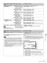
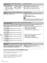
UB BINARY GP. [> Binary Gp.]:
Select the user bit binary
group flag of the timecode generator.
Note
When the TC MODE menu item is set to EXT REGEN, the
user-bit binary group flag setting follows the setting on the
timecode input to this unit.
*
000: NOT SPECIFIED [>> 000]:
Character set not specified
001: ISO CHARACTER [>> 001]:
8-bit characters conforming
to ISO 646 and ISO 2022
010: UNASSIGNED-1 [>> 010]:
Undefined
011: UNASSIGNED-2 [>> 011]:
Undefined
100: UNASSIGNED-3 [>> 100]:
Undefined
101: PAGE/LINE [>> 101]:
Multiplex
110: UNASSIGNED-4 [>> 110]:
Undefined
111: UNASSIGNED-5 [>> 111]:
Undefined
VITC POS SEL-1 [> VITC pos-1]:
Select a line where to
insert the VITC.
20 LINE [>> 20 line] to 12 LINE [>> 12 line]:
Select any line
from 12 to 20.
Factory default setting:
*
16 LINE [>> 16 line]
Notes
• You can insert the VITC signal in two places. To insert it in
two places, set both this item and also VITC POS SEL-2.
• The setting values are as follows when the system frequency
is set to 50i.
9 LINE [>> 9 line] to 22 LINE [>> 22 line]:
Select any line
from 9 to 22.
Factory default setting:
*
19 LINE [>> 19 line]
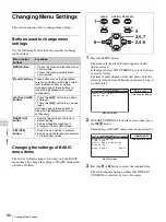
VITC POS SEL-2 [> VITC pos-2]:
Select a line where to
insert the VITC.
20 LINE [>> 20 line] to 12 LINE [>> 12 line]:
Select any line
from 12 to 20.
Factory default setting:
*
18 LINE [>> 18 line]
Notes
• You can insert the VITC signal in two places. To insert it in
two places, set both this item and also VITC POS SEL-1.
• The setting values are as follows when the system frequency
is set to 50i.
9 LINE [>> 9 line] to 22 LINE [>> 22 line]:
Select any line
from 9 to 22.
Factory default setting:
*
21 LINE [>> 21 line]
VITC OUTPUT [> VITC out]:
Select the timecode to be output
as VITC.
OFF [>> OFF]:
Do not output VITC.
TC [>> TC]:
Output TC after converting it to VITC.
*
VITC [>> VITC]:
Output VITC.
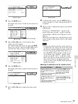
EE OUT PHASE [> EE out]:
Determine the output phase for
the LTC signal output from the TC OUT connector when
recording timecode and in STOP REC mode (forced E-E
mode).
*
NO OUTPUT [>> NO OUT]:
Suppress the output.
THROUGH [>> through]:
Output the timecode input to the TC
IN connector as it is.
VIDEO INPUT PHASE [>> V input]:
Output the timecode with
the same phase as the input video signal phase.
VIDEO OUTPUT PHASE [>> V output]:
Output the timecode
with the same phase as the output video signal phase.
MUTING IN SRCH [> Muting]:
Select whether to suppress
the output from the TC OUT connector in search (jog/
shuttle) mode.
OFF [>> OFF]:
Do not suppress.
*
ON [>> ON]:
Suppress.
TIME CODE [Time code]: Settings related to the timecode
generator
Description of settings


