83
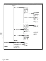
Menu Contents
Chap
te
r 7
Men
u
s
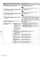
HD PROCESS CONTROL
[> HD Process]
ADJ RANGE [>> Adj range]:
Select the adjustment
range for video gain and
chrominance gain.
*
–3 to +3(db) [>>> –3/+3]:
–3 dB to +3 dB
WIDE [>>> wide]:
–
∞
to +3 dB
VIDEO GAIN [>> V gain]:
Set the video output
level.
000 [>>> 000] to 3FF [>>> 3FF]
Factory default setting:
*
200H
CHROMA GAIN [>> C gain]:
Set the chrominance
output level.
000 [>>> 000] to 3FF [>>> 3FF]
Factory default setting:
*
200H
CHROMA PHASE [>> C
phase]:
Set the
chrominance phase.
00 [>>> 000] to FF [>>> FF]
Factory default setting:
*
80H
SETUP LEVEL [>> Setup
lev]:
Set the setup level.
000 [>>> 000] to 3FF [>>> 3FF]
Factory default setting:
*
200H
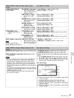
SYNC PHASE [> Sync
Phase]:
Adjust the sync
phase.
SYNC PHASE [>> Sync
phs]:
Adjust the
SYNC+SC phase.
000 [>>> 000] to 3FF [>>> 3FF]
Factory default setting:
*
Adjusted value at factory or 200H
SUB CARRIER [>> SC
phase]:
Adjust the
subcarrier phase.
000 [>>> 000] to 3FF [>>> 3FF]
Factory default setting:
*
Adjusted value at factory or 200H
INPUT BLANK [> Input blnk]
Note
Displayed only when the
system frequency is set to 50i.
LINE 335 [>> Line 335]:
Select whether to blank
line 335, or to output it as
part of the video signal.
*
BLANK [>>> blank]:
Blank.
THROUGH [>>> through]:
Output as a video signal.
AUDIO CONTROL [Audio]: Settings related to audio
control
Description of settings
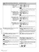
REC MODE [> REC mode]:
Select the audio recording mode.
*
2 CHANNEL (48kHz) [>> 2 ch]:
2-channel, 48-kHz mode
4 CHANNEL (32kHz) [>> 4 ch]:
4-channel, 32-kHz mode
INPUT ARRANGE [> Input arng]:
Make settings for input
audio mixing.
Notes
• When, in 4-channel mode, analog audio is selected for all
four channels (channels 1/2 and 3/4), the same analog
audio signals are recorded on channels 1 and 3 and on
channels 2 and 4, respectively. That is, the analog signal
recorded on channel 1 is also recorded on channel 3 and
the analog signal recorded on channel 2 is also recorded on
channel 4.
You can adjust the audio level on each of the four channels
separately using the REC/PB LEVEL control knobs with the
VARIABLE switch set to REC.
• When i.LINK (HDV) input is selected, the setting of this
menu item has no effect.
Set the channels on which to record the input audio signals as
follows.
(1) Use the
Mm<
/
A
,
/
B
buttons to move the cursor, and
use the SET (YES) button to toggle the setting on and off.
(2) To save the settings, press the MENU button to return to the
previous screen, then press the SET (YES) button.
Example settings:
1
Input audio channel 1 (“CH1”) is recorded on audio channel
1 (“CH1”) on tape.
2
Input audio channels 2 and 4 (“CH2” and “CH4”) are
recorded mixed on audio channel 2 (“CH2”) on tape.
3
Input audio channel 4 (“CH4”) is recorded on audio channel
3 (“CH3”) on tape.
4
Input audio channel 3 (“CH3”) is recorded on audio channel
4 (“CH4”) on tape.
VIDEO CONTROL [Video]: Settings related to video
control
Description of settings
A U D I O I N P U T S O U R C E
A R R A N G E
i n 1 i n 2 i n 3 i n 4
- - - - - - - - - - - - - - - - -
c h 1 : * o n
c h 2 : o n o n
c h 3 : o n
c h 4 o n
O N / O F F : S E T K E Y
T O M E N U : M E N U K E Y
1
2
3
4

