12
Installation
1
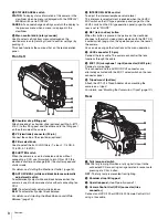
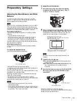
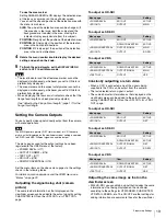
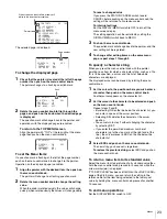
Loosen the viewfinder left-right positioning ring and
slide the viewfinder in the direction of arrow
A
.
The viewfinder stopper
B
automatically pops down.
2
Tighten the viewfinder left-right positioning ring to
secure the viewfinder at the most convenient
position.
3
Connect the viewfinder cable to the VF connector.
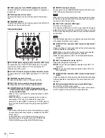
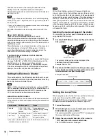
To adjust the viewfinder’s front-rear position
The viewfinder can slide in the range of 53 mm (2
1
/
8
inches).
Adjust the front-rear position so that you can easily operate it
on your shoulder.
1
Pulling the LOCK lever backward permits you to slide the
viewfinder backward or forward.
2
Adjust the viewfinder front-
rear position and
3
lock it by returning the lever forward to the
original position.
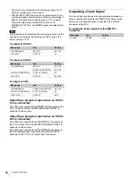
To detach the viewfinder
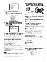
Loosen the viewfinder left-right positioning ring, pull the
viewfinder stopper, then pull out the viewfinder by sliding it in
the direction opposite to that when attached.
Status displays in the viewfinder
Besides the video image, the viewfinder can display
characters and messages showing the camera settings and
operation status, as well as items such as a center marker or
safety-zone marker.
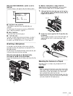
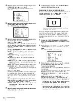
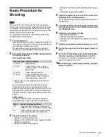
When the DISPLAY/MENU switch is set to DISPLAY
Items set to ON using the menu or related switches will be
displayed.
a
TALK indication
Displayed when the intercom microphone is set to ON.
b
EX (lens extender) indication
Displayed when a lens extender is in use.
c
Zoom position indication
Indicates the approximate position of the zoom lens variator
between wide angle (0) and telephoto (99).
d
Battery voltage indication
When the CAMERA POWER switch is set to EXT, the DC IN
voltage is displayed.
When the switch is set to CCU, the internal voltage of the
camera is displayed.
e
Focus position indication
Shows the focus position of a zoom lens as a numeric value (0
to 255 [infinity]).
f
5600K mode indication
Displayed when the internal electrical filter (5600K) is set to
ON.
g
Filter indication
Displays the type of ND filter currently selected with a number
(1, 2, 3, or 4).
h
White balance memory indication
Shows the currently selected white balance automatic
adjustment memory. This is not displayed when a CCU is
connected.
W:A:
The WHITE BAL switch is set to A.
W:B:
The WHITE BAL switch is set to B.
W:P:
The WHITE BAL switch is set to PRST.
i
Gain value indication
Shows the video gain value (dB) set with the GAIN switch.
j
Shutter/ECS indication
Displays the shutter/ECS status. Nothing is displayed if the
electronic shutter is set to OFF.
k
F-value indication
Indicates the lens F (iris opening) value.
RE
T 1
INCO
M
VF
A
B
1
2
3
1
2
3
LOCK
LOCK lever
F255
12.5V
EX Z55
1 A
F5.6
0dB 1/125
W:
5600
TALK
1
2
3
4
5
6
7
8
9
0
qa
Summary of Contents for HXC-100
Page 43: ...43 Appendices ...
Page 44: ...Printed in Japan ...


