background image

42

Appendices

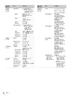
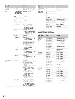
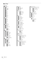
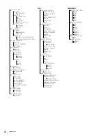
TEST OUT (M10)

OUTPUT

(PWR SAVE)

VBS-OUT

CHARACTER

GAIN

CHROMA

SETUP (UC model)

HD SYNC-OUT

V-PHASE

H-PHASE

SDI OUT (M11)

OUTPUT

(PWR SAVE)

CHARACTER

EMB AUDIO

(1-MIC1 2-MIC2)/(3-AES1 4-AES2)

(1-PGM1 2-PGM2)/(3-ENG 4-PROD)

POWER SAVE (M12)

SDI OUT

DOWN CONVERTER

PROMPTER

TRUNK (M13)

TRUNK

GENLOCK (M14)

REFERENCE

GENLOCK

STATUS

FORMAT

PHASE

V

HD H

SD H

DATE (M15)

DATE/TIME

BATTERY ALARM (M16)

BEFORE END

END

OTHERS 1 (M17)

FAN MODE

CAM BARS

V DTL CREATION

DTL H/V MODE

TEST2 MODE

WHITE SETUP MODE

ALAC

OTHERS 2 (M18)

DATE TYPE

F NO. DISP

EXT RETURN (M19)

SD ASPECT

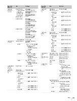
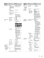
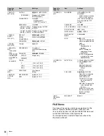
FILE

OPERATOR FILE (F01)

READ (MS

t

CAM)

WRITE (CAM

t

MS)

PRESET

STORE PRESET FILE

FILE ID

CAM CODE

DATE

SCENE FILE (F02)

1/2/3/4/5

STORE

STANDARD

READ (MS

t

CAM)

WRITE (CAM

t

MS)

FILE ID

CAM CODE

DATE

REFERENCE (F03)

STORE FILE

STANDARD

ALL PRESET

READ (MS

t

CAM)

WRITE (CAM

t

MS)

FILE ID

CAM CODE

DATE

LENS FILE (F04)

STORE FILE

No.

NAME

F NO

CENTER MARKER

H POS

V POS

STORE

OHB FILE (F05)

STORE FILE

FILE CLEAR (F06)

PRESET OPERATOR

REFERENCE (ALL)

10 SEC CLEAR

OHB WHITE SHADE (ALL)

OHB BLACK SHADE

OHB ND OFFSET

OHB MATRIX

M.S. FORMAT

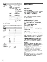
DIAGNOSIS

BOARD STATUS (D01)

OHB

DPR

CD

TX

SY

PS

PLD VERSION (D02)

TG

AT

VDAP

VSOP

ASSIST

DEMUX

DEMAP

ROM VERSION (D03)

AT

SERIAL NO. (D04)

MODEL

NO

Summary of Contents for HXC-100

Page 1: ...oroughly and retain it for future reference HXC 100 4 137 704 12 1 2009 Sony Corporation The supplied CD ROM includes operating instructions for the HXC 100 HD Color Camera English French German Italian and Spanish versions in PDF format For more details see Using the CD ROM Manuals on page 6 ...

Page 2: ...For the customers in Canada This Class A digital apparatus complies with Canadian ICES 003 Pour les clients au Canada Cet appareil numérique de la classe A est conforme à la norme NMB 003 du Canada For the customers in Europe This product with the CE marking complies with both the EMC Directive and the Low Voltage Directive issued by the Commission of the European Community Compliance with these d...

Page 3: ...erial special handling may apply See www dtsc ca gov hazardouswaste perchlorate Perchlorate Material Lithium battery contains perchlorate For the customers in Taiwan only Table of Contents Overview 4 Features 4 System Configuration 5 Standalone operation example 5 System operation example with a Camera Control Unit 6 Using the CD ROM Manuals 6 Parts Identification 7 Front right 7 Front left 8 Rear...

Page 4: ...he camera operator the type of lens in use or the shooting style A low repulsion shoulder pad position fixed is available as an option Part No A 8286 346 A Function assignable switches The camera has buttons to which various functions can be assigned on the side panel and the rear You can activate your desired function such as electronic color temperature conversion instantly when shooting by assi...

Page 5: ...iewfinder screen Furthermore there are various cautionary and warning indications to be occasionally displayed making it simple to check the status of the camera 1 Zebra pattern A stripe pattern displayed on the viewfinder screen which indicates the portions where the video level is above about 70 or 100 Used to check the video level of the subject Digital triax transmission The camera uses an ind...

Page 6: ...l the latest version you can download from the URL mentioned in Preparations above If you have lost or damaged the CD ROM you can purchase a new one to replace it Contact your Sony service representative a Supplied with the HDVF 550 C550W C730W Part No A 7612 405 E b 600 m 1969 ft at maximum and 50 m 164 ft at minimum when using Fujikura 8 5 mm dia cables For information of other cables see About ...

Page 7: ...hipped from the factory the values set are L 0 dB M 6 dB and H 12 dB k AUTO KNEE and output signal selection switch To select the signal color bar signal or camera s video signal to be used as output to a VTR the viewfinder or a video monitor when the camera is used in standalone status without connecting a CCU When the camera s video signal is being used as output the auto knee function can be se...

Page 8: ...alance BLK To automatically adjust black balance For details see Adjusting the Black Balance and White Balance page 15 f INTERCOM LEVEL control To adjust the intercom earphone volume level The intercom level adjustment is enabled when the LEVEL MIC switch on the UC type operation panel page 9 or the LEVEL switch on the CE type operation panel page 9 on the rear is set to FRONT g RET return video b...

Page 9: ...witch functions the same as the DISPLAY MENU switch on the front page 7 d ASSIGNABLE button You can assign a function with ASSIGNABLE REAR on the SWITCH ASSIGN1 page of the OPERATION menu e Menu control knob rotary encoder This knob functions the same as the menu control knob on the front page 8 f LEVEL MIC intercom level control microphone switch To determine whether to use the INTERCOM LEVEL con...

Page 10: ...f REMOTE connector 8 pin For connection to an RM B150 B750 Remote Control Unit or RCP 1000 series Remote Control Panel When a CCU is used in combination this connector functions as the trunk signal input output Do not connect any remote control device to this connector g TEST OUT connector BNC type To output an analog signal This supplies a VBS signal an HD Y signal equal to the signal output from...

Page 11: ...nformation on handling lenses refer to the operation manual for the particular lens 1 Push the lens fixing lever A upward and remove the lens mount cap from the lens mount 2 Align the lens alignment pin C with the notch B in the upper part of the lens mount and insert the lens into the mount 3 While supporting the lens push the lens fixing lever A downward to secure the lens 4 Connect the lens cab...

Page 12: ...or related switches will be displayed a TALK indication Displayed when the intercom microphone is set to ON b EX lens extender indication Displayed when a lens extender is in use c Zoom position indication Indicates the approximate position of the zoom lens variator between wide angle 0 and telephoto 99 d Battery voltage indication When the CAMERA POWER switch is set to EXT the DC IN voltage is di...

Page 13: ...ttach a microphone using a CAC 12 When attaching a long type microphone such as an ECM 674 678 use an optional CAC 12 Microphone Holder 1 1 Remove the front screw hole cover on the top then 2 fix the CAC 12 in place with the two screws B4 8 supplied with the CAC 12 2 Loosen the screw to open the CAC 12 and attach the microphone If the microphone diameter is small attach the adaptor A supplied with...

Page 14: ...move the lever in the direction of the arrow to return the pin to its original position It is not possible to mount a camera with the pin not seated Adjusting the Shoulder Pad Position You can shift the shoulder pad in the range of 28 mm 1 1 8 inches This adjustment helps you get the best balance for shooting with the camera on your shoulder To adjust 1 Raise the lever in the center of the shoulde...

Page 15: ...n memory will be preserved even when the camera power is turned off During black balance adjustment the iris will be automatically closed During black balance adjustment the gain switching circuit will work automatically and the viewfinder screen will flicker several times This is not a malfunction To adjust the white balance 1 Select the built in filter according to the lighting conditions with t...

Page 16: ...re as follows 1 The values in the table are those with 59 94i With other formats the available values may be different With artificial lighting particularly fluorescent lights and mercury vapor lamps the brightness appears to be constant but in fact the strength of the red green and blue components varies with the power supply frequency This phenomenon is known as flicker When using the electronic...

Page 17: ...ange focal length ring lock screw 4 With either manual or power zoom set the zoom ring to telephoto 5 Aim at the flange focal length adjustment chart and turn the focus ring to focus the image 6 Set the zoom ring to wide angle 7 Turn the Ff ring to bring the chart into focus Take care not to move the distance ring 8 Repeat steps 4 through 7 until the image is in focus at both telephoto and wide an...

Page 18: ...arities of a subject and converts the integrated values to a level indicator which shows the focus condition The focus setting where the indicator shows the maximum level is the best focus setting The range of the indicator substantially changes depending on picture elements or shooting environments Adjust it with GAIN and OFFSET as required 1 Display the CONTENTS page of the OPERATION menu referr...

Page 19: ... factory POWER SAVE U11 OUTPUT FORMAT U16 TEST OUT U17 SDI OUT U18 DOWN CONVERTER U19 Set the menu items on the above menu pages to the settings shown in the following tables For details on menu operations and the USER menu see Menus on page 22 Outputting the signal being shot camera picture The same textual information as that displayed on the viewfinder screen can be added to the output signal b...

Page 20: ... camera Outputting a prompter signal when an HSCU 300 is connected The VBS signal supplied to the PROMPTER 1 connector of the CCU is output from the PROMPTER GENLOCK RET IN connector of the camera The VBS signal supplied to the PROMPTER 2 connector or the SDI prompter signal supplied to the RETURN INPUT connector of the CCU is not output from the camera Outputting a Trunk Signal The trunk signal c...

Page 21: ...ERATION menu page 26 and the PAINT menu page 30 Electronic shutter setting page 16 Settings for the output signals from the camera page 19 Flange focal length setting page 17 4 Adjust the eyepiece focus as well as the contrast and brightness of the viewfinder image For viewfinder settings refer to the operation manual for the viewfinder 5 If required switch on the center marker and or safety zone ...

Page 22: ...ed page indication then push on the menu control knob PGM1 ENG PROD TRACKER PGM2 ASSIGNABLE 2 3 4 RET1 RET PROD ENG OFF LINE LEVEL REAR FRONT MIC DISPLAY MENU OFF INTERCOM EARPHONE DISPLAY MENU switch STATUS CANCEL switch Menu control knob Push on Rotate Front right Rear operation panel DISPLAY MENU switch Menu control knob Push on Rotate Menu Purpose USER This menu can include menu pages selected...

Page 23: ...string such as a file ID is to be specified a cursor and the list of selectable characters are displayed The displayed cursor can be moved by rotating the menu control knob 1 Set the cursor to the position where you wish enter a character then push on the menu control knob Another cursor appears on the character list 2 Set the cursor to the character to be entered and push on the menu control knob...

Page 24: ...R 19 EDIT then push on the menu control knob to display the page If a different page is displayed turn the menu control knob until the desired page appears then push on the menu control knob to select the page Example When you select the USER 2 EDIT page 3 Move the pointer to the item to be added this operation is unnecessary if no item exists on the page as shown in the figure for the previous st...

Page 25: ...item You cannot insert a blank line on a page where 10 items have already been registered Editing by pages You can add a page to the USER menu delete a page from the USER menu or replace pages using the EDIT PAGE of the USER MENU CUSTOMIZE menu To add a page 1 Select USER MENU CUSTOMIZE on the TOP MENU screen If this is the first time the USER MENU CUSTOMIZE menu has been displayed the CONTENTS pa...

Page 26: ...ASSIGN1 moves to the 04 position and the VF DISPLAY and following pages move down one line OPERATION Menu These remarks are common for all the following menu tables ON OFF 0 in the Settings columns Default settings Page No nn Unn For the pages that have been registered on the USER menu at the factory the USER menu page numbers are indicated in parenthesis Execute by ENTER Execute by pushing on the...

Page 27: ... NORMAL UC model 59 94i 50i 59 94P 50P CE model 59 94i 50i 59 94P 50P Page title Page No Item Settings VF MARKER 03 U06 MARKER ON OFF WHITE BLACK DOT CENTER ON OFF 1 2 3 4 1 Entire cross 2 Entire cross with a hole 3 Center 4 Center with a hole SAFETY ZONE ON OFF 80 0 90 0 92 5 95 0 EFFECT ON OFF FOCUS FOCUS Displayed when INDICATOR of FOCUS ASSIST is ON ASPECT ON OFF 16 9 15 9 14 9 13 9 4 3 MASK O...

Page 28: ... VF SCAN 16 9 4 3 Page title Page No Item Settings SWITCH ASSIGN1 09 U09 GAIN L 3 0 3 6 9 12 dB M 3 0 3 6 9 12 dB H 3 0 3 6 9 12 dB ASSIGNABLE 1 UC model OFF RETURN1 SW RETURN2 SW INCOM VF DETAIL MIX VF 5600K FAN MAX CE model OFF RETURN1 SW RETURN2 SW ENG PROD VF DETAIL MIX VF 5600K FAN MAX ASSIGNABLE 2 UC model OFF RETURN1 SW RETURN2 SW INCOM VF DETAIL MIX VF 5600K FAN MAX CE model OFF RETURN1 SW...

Page 29: ...GHT BOTH TRACKER LEFT RIGHT BOTH Page title Page No Item Settings RECEIVE SEL2 14 TRACKER RECEIVE SELECT SEPARATE MIX INTERCOM UC model only LEFT RIGHT BOTH TALK CE model only LEFT RIGHT BOTH ENG CE model only LEFT RIGHT BOTH PROD CE model only LEFT RIGHT BOTH PGM1 LEFT RIGHT BOTH PGM2 LEFT RIGHT BOTH RECEIVE SEL3 15 EARPHONE RECEIVE SELECT SEPARATE MIX INTERCOM UC model only LEFT RIGHT BOTH ENG C...

Page 30: ...1 to 5 4 MASTER 3 0dB to 12 0dB 0 0dB GAMMA P04 LEVEL R G B M 99 to 99 0 COARSE 0 35 to 0 45 to 0 90 0 05 steps TABLE STANDARD HYPER With STANDARD selected UC model 1 2 3 4 5 6 7 CE model 1 2 3 4 5 6 7 1 equivalent to a camcorder 2 4 5 times gain 3 3 5 times gain 4 equivalent to SMPTE 240M 5 equivalent to ITU R709 6 5 0 times gain 7 5 0 times gain 709 With HYPER selected 1 2 3 4 1 325 to 100 2 460...

Page 31: ...ATIO 99 to 99 0 FREQ 99 to 99 0 MIX RATIO 99 to 99 0 KNEE APT 99 to 99 0 ON OFF ABS When highlighted ABS mode H V RATIO FREQ MIX RATIO and KNEE APT are displayed in absolute values Page title Page No Item Settings SKIN DETAIL P11 SKIN DTL ON OFF SKIN GATE ON OFF MAT MAT Displayed when GATE of MULTI MATRIX is ON AUTO HUE Execute by ENTER PHASE 0 to 359 WIDTH 0 to 90 29 SAT 99 to 99 89 LEVEL 99 to 9...

Page 32: ...50 1 500 1 1000 1 2000 sec ECS FREQ 59 94i 60 00 to 4300 Hz 60 00 Hz UC model 50i 50 00 to 4700 Hz 50 00 Hz CE model 59 94P 59 96 to 4600 Hz 50P 50 03 to 4600 Hz Page title Page No Item Settings SCENE FILE P15 See FILE menu F02 1 To store and read scene files paint data 2 3 4 5 STORE STANDARD Execute by ENTER READ MS CAM Execute by ENTER WRITE CAM MS Execute by ENTER FILE ID Max 16 characters CAM ...

Page 33: ... 60 dB FRONT MIC 48V ON OFF Page title Page No Item Settings 1 2 3 4 5 6 CALL TALLY M07 Invalid when no CCU connected CCU CALL ON OFF CAM CALL ON OFF OUTPUT FORMAT M08 U16 CURRENT Displays the current format ACTIVE LINE Not displayed when a CCU connected UC model 1080 59 94i 1080 50i 720 59 94P 720 50P CE model 1080 59 94i 1080 50i 720 59 94P 720 50P When you change the ACTIVE LINE setting once tu...

Page 34: ...4 to 1023 0 HD H 1700 to 1700 0 SD H 1024 to 1023 0 DATE M15 DATE TIME yyyy mm dd hh mm BATTERY ALARM M16 BEFORE END 11 5 V to 17 0 V END 11 0 V to 11 5 V Page title Page No Item Settings OTHERS 1 M17 FAN MODE OFF AUTO1 AUTO2 MIN MAX AUTO1 Normal rotation AUTO2 Slow rotation The internal temperature may raise with the OFF setting CAM BARS ON OFF V DTL CREATION NAM G R G Y DTL H V MODE H V V Only T...

Page 35: ...ick See To specify a character string on page 23 CAM CODE Camera code display only DATE Date display only REFERENCE F03 STORE FILE Execute by ENTER To store the current settings of the reference file items in the reference file in internal memory STANDARD Execute by ENTER To read the standard values in the reference file in internal memory ALL PRESET Execute by ENTER To resume the factory preset r...

Page 36: ...are specific to CCD Charge Coupled Device image sensors They do not indicate malfunctions White flecks Although the CCD image sensors are produced with high precision technologies fine white flecks may be generated on the screen in rare cases caused by cosmic rays This is related to the principle of CCD image sensors and is not a malfunction The white flecks especially tend to be seen when operati...

Page 37: ...ch enables you to share data among cameras Usable types of Memory Stick You can use a Memory Stick a Memory Stick Duo a Memory Stick PRO a Memory Stick PRO Duo and a MagicGate Memory Stick with this product You can use a Memory Stick Duo or a Memory Stick PRO Duo without any adaptor However the MagicGate copyright protection1 is not valid with this product 1 MagicGate is copyright protection techn...

Page 38: ...r applicable laws The Memory Stick application software may be modified or changed by Sony without prior notice Specifications Notes OFF MENU STATUS CANCEL Access lamp Label side Memory Stick Terminal Write protect tab Labelling position Memory Stick and are trademarks of Sony Corporation Memory Stick Duo is a trademark of Sony Corporation Memory Stick PRO and are trademarks of Sony Corporation Me...

Page 39: ...eturn Video Selector VCT U14 Tripod Adaptor Memory Stick Low repulsion Shoulder Pad A 8286 346 A Shoulder Strap A 6772 374 C Related equipment Camera Control Unit HXCU 100 HSCU 300 HKCU FP1 Option Panel RCP 1000 series Remote Control Panel RM B150 B750 Remote Control Unit Dimensions 263 10 3 8 105 4 1 4 184 7 1 4 363 14 3 8 136 5 3 8 Unit mm inches Note Always verify that the unit is operating pro...

Page 40: ...EIGHT VF OUT 08 VF OUT RET MIX VF MIX DIRECTION MX VF MODE MX VF LEVEL VF SCAN SWITCH ASSIGN 1 09 GAIN ASSIGNABLE 1 ASSIGNABLE 2 ASSIGNABLE REAR RE ROTATION SWITCH ASSIGN 2 10 LENS VTR S S FRONT RET2 HANDLE SW1 HANDLE SW2 ZOOM SPEED HEAD SET 11 INTERCOM MIC LEVEL POWER UNBAL INTERCOM LEVEL 12 SIDE TONE RECEIVE SEL1 13 INTERCOM RECEIVE SELECT INTERCOM UC model ENG CE model PROD CE model PGM1 PGM2 T...

Page 41: ...ABS USER MATRIX P12 R G R B G R G B B R B G MATRIX PRESET USER MULTI MULTI MATRIX P13 PHASE HUE SAT ALL CLEAR GATE MATRIX PRESET USER MULTI SHUTTER P14 SHUTTER ECS FREQ SCENE FILE P15 1 2 3 4 5 STORE STANDARD READ MStCAM WRITE CAMtMS FILE ID CAM CODE DATE MAINTENANCE AUTO SETUP M01 AUTO BLACK AUTO WHITE AUTO LEVEL AUTO WHITE SHADING AUTO BLACK SHADING TEST WHITE SHADING M02 V SAW V PARA H SAW H PA...

Page 42: ...ERS 2 M18 DATE TYPE F NO DISP EXT RETURN M19 SD ASPECT FILE OPERATOR FILE F01 READ MStCAM WRITE CAMtMS PRESET STORE PRESET FILE FILE ID CAM CODE DATE SCENE FILE F02 1 2 3 4 5 STORE STANDARD READ MStCAM WRITE CAMtMS FILE ID CAM CODE DATE REFERENCE F03 STORE FILE STANDARD ALL PRESET READ MStCAM WRITE CAMtMS FILE ID CAM CODE DATE LENS FILE F04 STORE FILE No NAME F NO CENTER MARKER H POS V POS STORE O...

Page 43: ...43 Appendices ...

Page 44: ...Printed in Japan ...

Reviews: