58
Menu List
Cha
p
te
r 4
Men
u
and
Det
a
iled Set
tings
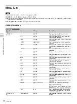
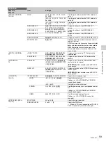
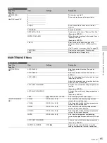
<VF DETAIL>
05 (U02)
Note
The VF detail function is
activated only when either
the CBK-VF01 or DXF-
C50WA viewfinder is
attached to the camera.
VF DETAIL
ON
, OFF
Adds detail signals to the edges of the subject.
0 to 100%
25%
CRISP
-99 to 99
0
Removes faint detail signals
FREQUENCY
9M
, 14M, 18M
Changes the detection range for the edge.
FAT MODE
ON,
OFF
Strengthens the added detail signals.
AREA
100%
, 70%, 60%, 50%, 40%
Selects the area displaying the detail signals.
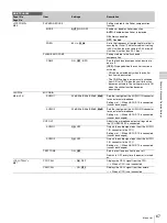
ZOOM LINK
0%, 25%, 50%, 75%,
100%
Sets the VF detail level at the full WIDE
position. (Changes the VF detail level according
to the zoom position.)
COLOR DETAIL
ON,
OFF
Displays the detail signals in colors.
BLUE
, RED, YELLOW
PEAK COLOR
ON,
OFF
Displays the strongest detail signal in colors.
CHROMA LEVEL
100%, 50%,
25%
, 0%
Lowers the chroma level. (Available only for
video signals used in viewfinders)
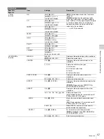
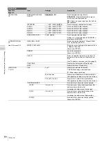
<FOCUS ASSIST>
06 (U03)
INDICATOR
ON,
OFF
, (EFFECT)
Displays or hides the focus assist indicator in
the viewfinder.
(EFFECT):
Displayed when EFFECT of <VF
MARKER> is ON.
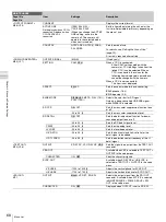
MODE
BOX
, B&W, COL
Sets the indicator position and format.
BTM
, LEFT, TOP, RIGHT
LEVEL
1 to 5
3
Sets the brightness and response speed of the
indicator.
QUICK
, SMOOTH
GAIN
0 to 99
50
Sets the gain of the indicator.
OFFSET
0 to 99
50
Automatically sets the offset value according to
the AREA MARKER SIZE and MASTER GAIN
settings.
AREA MARKER
ON,
OFF
, (ASPECT)
Displays or hides the detection area of the focus
as a marker in the viewfinder.
(ASPECT):
Displayed when ASPECT SAFETY
of <VF MARKER> is ON.
SIZE
SMALL,
MIDDLE
, LARGE
Changes the detection range. (If larger range
than needed is selected, both the subject and
background are detected. This may prevent the
indicator to function properly.
POSITION
LEFT,
CENTER
, RIGHT
Roughly sets the position of the detection area.
POSITION H
0 to 99
50
Finely adjusts the position of the detection area
in the horizontal directions.
POSITION V
0 to 99
50
Finely adjusts the position of the detection area
in the vertical directions.
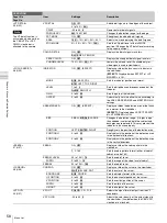
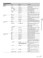
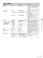
<ZEBRA>
07 (U07)
ZEBRA
ON,
OFF
Displays or hides the zebra pattern in the
viewfinder.
1
, 2, 1&2
Sets the zebra pattern format (either of zebra1,
zebra2 or zebra1&2)
ZEBRA1 LEVEL
50 to 109%
70
Sets the zebra1 level.
WIDTH
0 to 30%
10
Sets the range of the video level of zebra1.
ZEBRA2
50 to 109%
100
Sets the zebra2 level.
<CURSOR>
08 (U08)
CURSOR
ON,
OFF
Displays or hides the cursor in the viewfinder.
WHITE
, BLACK, DOT
Sets the color of the cursor.
BOX/CROSS
BOX
, CROSS
Sets the display format of the cursor.
H POSITION
0 to 99
50
Sets the horizontal position of the cursor.
V POSITION
0 to 99
50
Sets the vertical position of the cursor.
WIDTH
0 to 99
50
Sets the width of the cursor.
HEIGHT
0 to 99
50
Sets the height of the cursor.
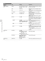
<VF OUT>
09 (U01)
VF OUT
COLOR
, Y, R, G, B
Selects the signal format output from the VF
connectors.
VF COLOR
-99 to 99
0
Adjusts the color density of the output signal to
the viewfinder. (Available when the CBK-VF01
viewfinder is attached.)
OPERATION
Page title
Page No.
Item
Settings
Description
Summary of Contents for HXC-D70 Series
Page 83: ......


