background image

1

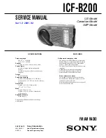
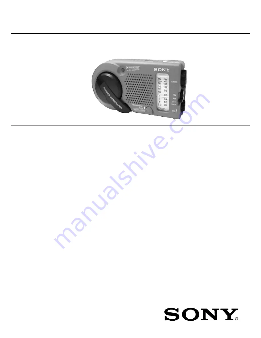
ICF-B200

SERVICE MANUAL

US Model

Canadian Model

AEP Model

Ver 1.0  2001. 01

FM/AM RADIO

Ver 1.3  2001. 02

Sony Corporation

Audio Entertainment Group

General Engineering Dept.

9-925-744-13

2001B0400-1

© 2001. 2

Frequency range

FM : 87.5 – 108 MHz
AM : 530 – 1,605 kHz

Speaker

Approx. 4.5 cm (1 

3

/

4

 inches) dia., 8 ohms

Power output

60 mW (Using the built-in rechargeable
battery)
90 mW (Using size AA (R6) dry batteries, not
supplied)

Output

v

 jack (minijack)

Power requirements

Built-in nickel-cadmium (2.4 V, 300 mAh,
Ni-Cd) battery or 3 V DC, two size AA (R6) dry
batteries

Dimensions

Approx. 163 

×

 80 

×

 55 mm (w/h/d)

(6 

1

/

2


×

 3 

1

/

4


×

 2 

1

/

4

 in)

Mass

Approx. 320 g (11.3 oz)
Approx. 355 g (12.6 oz) incl. batteries and
projecting parts

Supplied accessory

Hand strap (1)

Design and specifications are subject to change
without notice.

SPECIFICATIONS

Self-powered emergency radio

• You may use the radio right away by turning the

handle of the power generator, which charges the
built-in nickel-cadmium (Ni-Cd) rechargeable
battery. —Hand generating function

• You may also use size AA (R6) dry batteries (not

supplied).

• Audio Beacon that alerts the surroundings.
• Useful dial light when tuning in the dark.
• Water-resistant for all weather operation*.

*

Do not emmerse in water

This product is designed to be water-resistant,
but should not be emmersed in water or come in
continuous contact with water.
Before installing the batteries, be sure to wipe off
drops of water on the unit.

FEATURES

Summary of Contents for ICF-B200

Page 1: ...Approx 320 g 11 3 oz Approx 355 g 12 6 oz incl batteries and projecting parts Supplied accessory Hand strap 1 Design and specifications are subject to change without notice SPECIFICATIONS Self powered emergency radio You may use the radio right away by turning the handle of the power generator which charges the built in nickel cadmium Ni Cd rechargeable battery Hand generating function You may als...

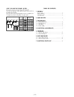
Page 2: ...re the ceramic filter must change two pieces together since it s supply two pieces in one package as a spare parts TABLE OF CONTENTS 1 GENERAL Power Sources 3 Playing the Radio 3 Useful functions 3 2 SERVICE NOTE 4 3 DISASSEMBLY 3 1 Cabinet Rear Assy 5 3 2 Main Board Assy 5 3 3 Main Board 6 3 4 Pointer Setting 6 4 ELECTRICAL ADJUSTMENTS 7 5 DIAGRAMS 5 1 Printed Wiring Boards 9 5 2 Schematic Diagra...

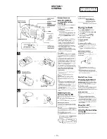
Page 3: ... 3 SECTION 1 GENERAL This section is extracted from instruction manual ...

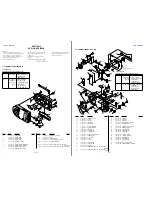
Page 4: ...o the telescopic antenna mounting points on the cabinet rear the battery terminals and all around the rib of the cabinet front assy sealant TSE392 W 7 432 950 03 SONY grease SGL 505 7 662 010 04 sealant TSE392 W 7 432 950 03 Apply SONY grease SGL 505 7 662 010 04 to the knobs and gears at the points specified in the figure with an applicator or other means cabinet rear cabinet front assy grease ap...

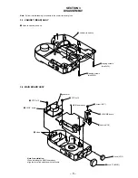
Page 5: ...SY 4 cabinet rear assy 3 tapping screws bind 2x20 2 tapping screws bind 2x20 3 PTP 3x10 5 generator 4 PTP 3x10 MAIN board assy 8 screw M1 7 9 VOLUME board º holder VOL 7 JACK board 6 claws 2 knob VOL 1 knob TUNING Note for installation When installing the MAIN board assy align the two slide switches with the levers SECTION 3 DISASSEMBLY ...

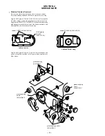
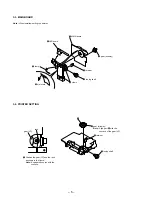
Page 6: ...oard 3 gear midway 1 retainer 2 tuning shaft 6 claws 5 lamp 8 LED board 4 dial scale gear VC rack A 2 gear midway Note Align part A with the concave of the gear VC 4 retainer 3 tuning shaft 1 Position the gear VC and the rack as shown in the figure Note Engage the convex with the concave ...

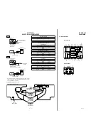
Page 7: ...aximum reading on level meter L1 CT4 620 kHz 1 400 kHz FM FREQUENCY COVERAGE ADJUSTMENT Adjust for a maximum reading on level meter L4 CT1 86 5 MHz 109 5 MHz FM TRACKING ADJUSTMENT Adjust for a maximum reading on level meter L2 CT2 86 5 MHz 109 5 MHz AM TRACKING ADJUSTMENT FM TRACKING ADJUSTMENT AM FREQUENCY COVERAGE ADJUSTMENT FM FREQUENCY COVERAGE ADJUSTMENT T1 AM IF ADJUSTMENT L1 CT4 L3 CT3 L4 ...

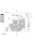
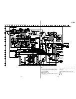
Page 8: ...2 D 9 IC3 E 8 Q1 F 11 Q2 G 4 Q3 H 4 Q4 C 8 Q5 D 8 Q6 D 8 Q7 E 6 Q8 E 7 Q11 E 7 Q12 H 3 Q13 E 3 ICF B200 5 1 PRINTED WIRING BOARDS Note X parts extracted from the component side Y parts extracted from the conductor side W indicates side identified with part number internal component b Pattern from the side which enables seeing ...

Page 9: ...nternal component 2 nonflammable resistor C panel designation U B Line H adjustment for repair Power voltage is dc 3 V and fed with regulated dc power supply from battery terminal Voltage is dc with respect to ground under no signal detuned condition no mark FM AM BUZZER ON Voltages are taken with a VOM Input impedance 10 MΩ Voltage variations may be noted due to normal production toler ances Sign...

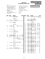
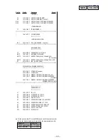
Page 10: ...TE CLICK 59 1 667 678 11 VOLUME BOARD 60 2 646 154 11 SCREW M1 7X5 61 3 018 881 01 SLIDER POLYETHYLENE 62 3 018 943 01 SPRING LIGHT 63 3 018 884 11 SCALE DIAL 64 3 018 871 01 RACK 65 3 018 870 01 POINTER 66 3 020 689 01 PIN PARALLEL 68 3 900 147 01 SHAFT TUNING 69 3 900 149 01 RETAINER 70 X 3374 974 1 CABINET FRONT ASSY INCLUDING SP1 ORANGE 70 X 3380 348 1 CABINET FRONT ASSY INCLUDING SP1 BLUE 71 ...

Page 11: ...OARD COMPLETE INCLUDING LED BOARD 3 018 873 01 CHASSIS COMBINED 3 314 712 01 SHEET CHLORIDE VINYL 3 363 895 01 SCREW M1 7 CAPACITOR C1 1 163 222 11 CERAMIC CHIP 5PF 0 25PF 50V C2 1 163 235 11 CERAMIC CHIP 22PF 5 50V C3 1 163 713 91 CERAMIC CHIP 27PF 5 50V C4 1 163 092 00 CERAMIC CHIP 9PF 0 25PF 50V C5 1 163 251 11 CERAMIC CHIP 100PF 5 50V C6 1 163 021 11 CERAMIC CHIP 0 01uF 10 50V C7 1 124 261 00 ...

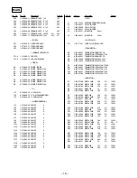
Page 12: ...3 11 COIL AIR CORE L3 1 406 028 00 COIL OSC AM L4 1 416 504 11 COIL AIR CORE L5 1 412 943 11 INDUCTOR 2 2uH L6 1 406 680 11 INDUCTOR 33mH PILOT LAMP PL1 1 517 710 11 LAMP PILOT BACK LIGHT TRANSISTOR Q2 8 729 800 71 TRANSISTOR 2SB815B7 TB Q3 1 801 806 11 TRANSISTOR DTC144EKA T146 Q4 8 729 800 71 TRANSISTOR 2SB815B7 TB Q5 8 729 120 28 TRANSISTOR 2SC1623 L5L6 Q6 8 729 120 28 TRANSISTOR 2SC1623 L5L6 Q...

Page 13: ...CKING MATERIALS 3 019 238 01 STRAP US Canadian 3 228 890 01 STRAP AEP 3 861 125 12 MANUAL INSTRUCTION ENGLISH US 3 861 125 21 MANUAL INSTRUCTION ENGLISH FRENCH Canadian 3 861 125 31 MANUAL INSTRUCTION ENGLISH FRENCH GERMAN SPANISH AEP HARDWARE LIST 1 7 623 507 01 LUG 2 6 2 7 624 104 04 STOP RING 2 0 TYPE E 3 7 624 113 04 STOP RING 9 0 TYPE E 4 7 626 202 51 PIN SPLIT 1X12 5 7 627 556 37 SCREW PRECI...

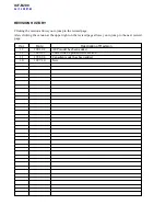
Page 14: ...evised page Also clicking the version at the upper right on the revised page allows you to jump to the next revised page Ver Date Description of Revision 1 3 2001 02 AEP model has been added 1 2 2000 03 Correct the Exploded views section 1 1 1998 08 Canadian model has been added 1 0 1997 10 New ...

Reviews: