PCS-G50/G50P
1-2
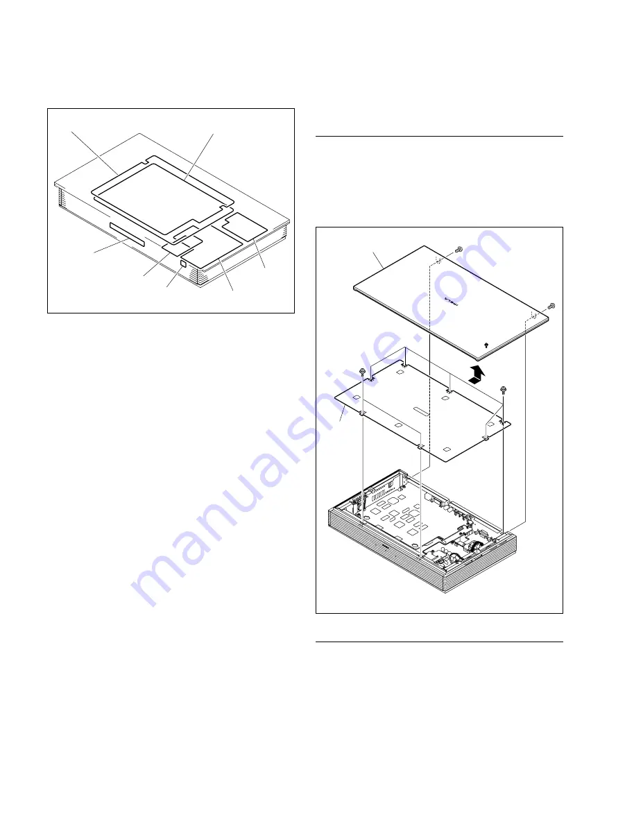
PS-686 board
SW-1259 board
LED-433 board
MS-73 board
CN-2635 board
CPU-382 board
DSP-113 board
Upper panel assembly
Top cover
assembly
B3
x
6
B3
x
6
PSW3
x
6
PSW3
x
6
1-3. Board Location
1-4. Removing/Reattaching the Cabinets
1-4-1. Top Cover Assembly
Removal
1.
Remove the two screws (B3
x
6), and remove the
upper panel assembly in the direction of the arrow.
2.
Remove the seven screws (PSW3
x
6), and lift the top
cover assembly.
Installation
3.
Reattach the top cover assembly in the reverse order of
steps 1 and 2.
Summary of Contents for Ipels PCS-G50
Page 6: ......
Page 16: ......
Page 26: ......
Page 34: ......
Page 170: ......
Page 186: ......
Page 191: ...PCS G50 G50P 8 7 8 7 CPU 382 B SIDE SUFFIX 12 13 A B C D 1 2 3 4 CPU 382 CPU 382 ...
Page 198: ......
Page 199: ......
Page 200: ...Printed in Japan Sony Corporation 2005 6 22 2005 PCS G50 UC PCS G50P CE E 9 968 181 01 ...


