PCS-G50/G50P
4-1
Section 4
Operation Check and Troubleshooting
This Section describes the procedures for checking the
equipment mainly by the self-diagnosis function and
troubleshooting.
Always perform the operation check after repairing or
replacing the boards of the unit.
4-1. Self-diagnosis Function
When starting the unit in Diag mode, an operation check
can be done using the self-diagnosis function. To start the
Diag mode, conduct a serial communicaton between the
unit and the terminal PC, and start the terminal software.
n
It is recommended that the latest application software to be
installed before starting the repairing procedure because
the built-in flash memory may be erased. (Refer to Section
4-4.)
4-1-1. Connecting the Terminal PC
1.
Connect the AUX CONTROL connector of the unit
and the serial port of the terminal PC with the RS-
232C cross cable.
2.
Turn on the power of the unit and the terminal PC.
3.
Start the terminal software (ex: Hiper Terminal) in the
terminal PC.
4.
Set the communication conditions of the terminal
software as follows.
baud rate:
38400 bps
Data:
8 bit
Start bit:
1 bit
Stop bit:
1 bit
Parity:
None
Flow control:
Xon/Xoff
4-1-2. Starting the Diag Mode
There are two methods to start the Diag mode.
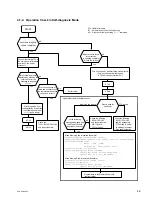
Decide which method to use according to the flow chart
and description.
Method 1
1.
Connect the unit and the terminal PC.
(Refer to Section 4-1-1.)
2.
Turn on the power of the terminal PC only.
3.
Start the terminal software in the terminal PC.
n
At this time, be sure to activate the terminal window.
4.
Turn on the power of the unit while pressing the [Ctrl]
+
D keys on the terminal PC.
Method 2
1.
Connect the unit and the terminal PC.
(Refer to Section 4-1-1.)
2.
Turn on the power of the unit and the terminal PC.
3.
Start the terminal software in the terminal PC.
4.
After starting the application (normal startup), enter
“
goto diag
” in the terminal PC from the command
prompt of the terminal software.
Summary of Contents for Ipels PCS-G50
Page 6: ......
Page 16: ......
Page 26: ......
Page 34: ......
Page 170: ......
Page 186: ......
Page 191: ...PCS G50 G50P 8 7 8 7 CPU 382 B SIDE SUFFIX 12 13 A B C D 1 2 3 4 CPU 382 CPU 382 ...
Page 198: ......
Page 199: ......
Page 200: ...Printed in Japan Sony Corporation 2005 6 22 2005 PCS G50 UC PCS G50P CE E 9 968 181 01 ...


