PCS-G50/G50P
4-26
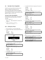
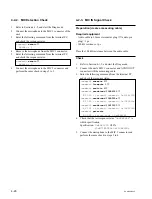
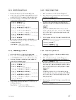
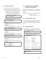
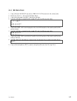
4-2-2. MIC Detection Check
1.
Refer to Section 4-1-2, and start the Diag mode.
2.
Connect the microphone to the MIC 1 connector of the
unit.
3.
Enter the following command from the terminal PC,
and check the response status.
command> extmic
↓
ExtMic : 1
4.
Remove the microphone from the MIC 1 connector.
5.
Enter the following command from the terminal PC,
and check the response status.
command> extmic
↓
ExtMic : 0
6.
Connect the microphone to the MIC 2 connector and
perform the same check in steps 2 to 5.
4-2-3. MIC IN Signal Check
Preparation (create a measuring cable)
Required equipment
.
Audio cable (ø3.5 mm stereo mini plug
5
audio pin
plug) : 1 pc
.
100 k
Z
resistance: 1pc
Place the 100 k
Z
resistance between the audio cable.
Check
1.
Refer to Section 4-1-2, and start the Diag mode.
2.
Connect the unit’s MIC 1 connector and AUDIO OUT
connector with the measuring cable.
3.
Enter the following command from the terminal PC,
and check the response status.
command> auxmute 1
↓
command> linemute 1
↓
command> audioin 0
↓
command> sendeccmd 10684000
↓
EC DSP : transmit command = 0x10684000
command> sendeccmd 1069000a
↓
EC DSP : transmit command = 0x1069000a
command> sendeccmd 10620000
↓
EC DSP : transmit command = 0x10620000
command> getecsts
EC DSP : return code = 0xXXXXXXX
4.
Check that the last response status “
0xXXXXXXX
” is
within specification.
Specification:
0xE4E1C00
±
20%
(
0xB71B000
to
0x112A8800
)
5.
Connect the microphone to the MIC 2 connector and
perform the same check in steps 2 to 4.
Summary of Contents for Ipels PCS-G50
Page 6: ......
Page 16: ......
Page 26: ......
Page 34: ......
Page 170: ......
Page 186: ......
Page 191: ...PCS G50 G50P 8 7 8 7 CPU 382 B SIDE SUFFIX 12 13 A B C D 1 2 3 4 CPU 382 CPU 382 ...
Page 198: ......
Page 199: ......
Page 200: ...Printed in Japan Sony Corporation 2005 6 22 2005 PCS G50 UC PCS G50P CE E 9 968 181 01 ...


