50
Overview
Configuration Examples
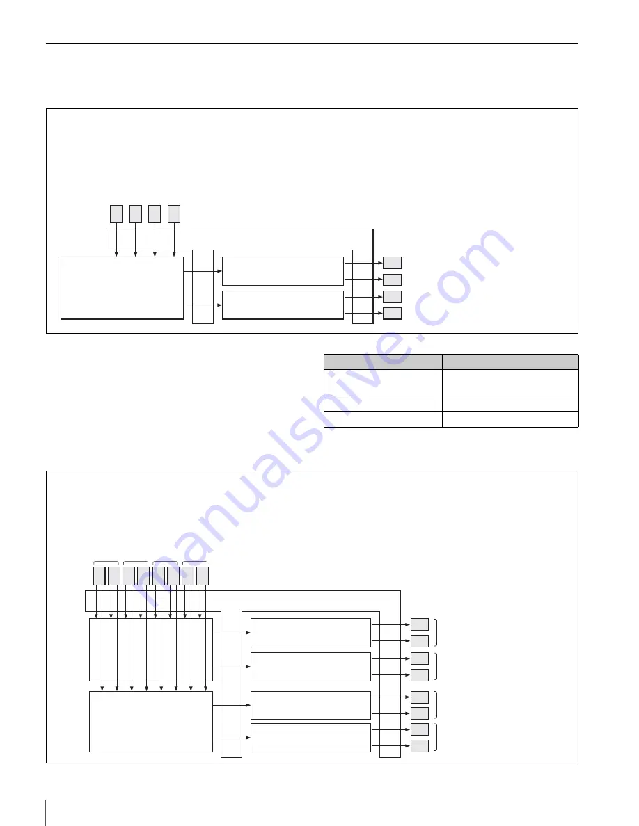
Hybrid configuration examples for the IXS-6600
With the above configuration, several routing switchers,
each of which can handle a different signal format, can be
configurated within a single chassis enclosure.
The crosspoint size for each signal format is as follows:
Hybrid configuration examples for the IXS-6700
17
17
34
7
16
16
32
7
Matrix Board
128 × 68
HD/SD Video Router
Processor Board
17 HD/SD Digital Video Output Board
Audio/Data Router
Processor Board
16
H
D
/S
D
D
ig
ita
l V
id
eo
In
pu
t B
oa
rd
16
S
D
D
ig
ita
l V
id
eo
In
pu
t B
oa
rd
32
D
-s
ub
A
E
S
/E
B
U
(b
al
an
ce
d)
In
pu
t B
oa
rd
7
R
S
-4
22
In
pu
t B
oa
rd
17 SD Digital Video Output Board
34 D-sub AES/EBU (balanced) Output Board
7 RS-422 Output Board
Mother board
Number
of inputs
P
ro
d
u
ct
n
am
e
Number
of outputs
Product name
Signal format
Matrix size
SDI router section
32 × 34 (of which, 16 × 17 for
HD SDI)
Digital audio router section 32 × 34
RS-422A router section
14 ports
16
17
17
17
17
34
34
7
7
16 16 16 32 32
7
7
Matrix Board
128 × 68
HD/SD Video Router
Processor Board
Audio/Data Router
Processor Board
17 HD/SD Digital Video Output
Board
SD Video Router
Processor Board
Audio/Data Router
Processor Board
Matrix Board
128 × 68
16
H
D
/S
D
D
ig
ita
l V
id
eo
In
pu
t B
oa
rd
16
S
D
D
ig
ita
l V
id
eo
In
pu
t B
oa
rd
32
D
-s
ub
A
E
S
/E
B
U
(b
al
an
ce
d)
In
pu
t B
oa
rd
7
R
S
-4
22
In
pu
t B
oa
rd
17 SD Digital Video Output Board
34 D-sub AES/EBU (balanced)
Output Board
7 RS-422 Output Board
Mother board
Number
of inputs
P
ro
d
u
ct
n
am
e
Number
of outputs
Product name


