background image

(Supplementary 

information) 

TV Business Division 

20 

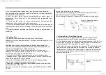
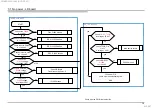
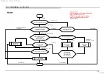
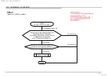
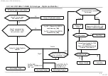
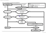
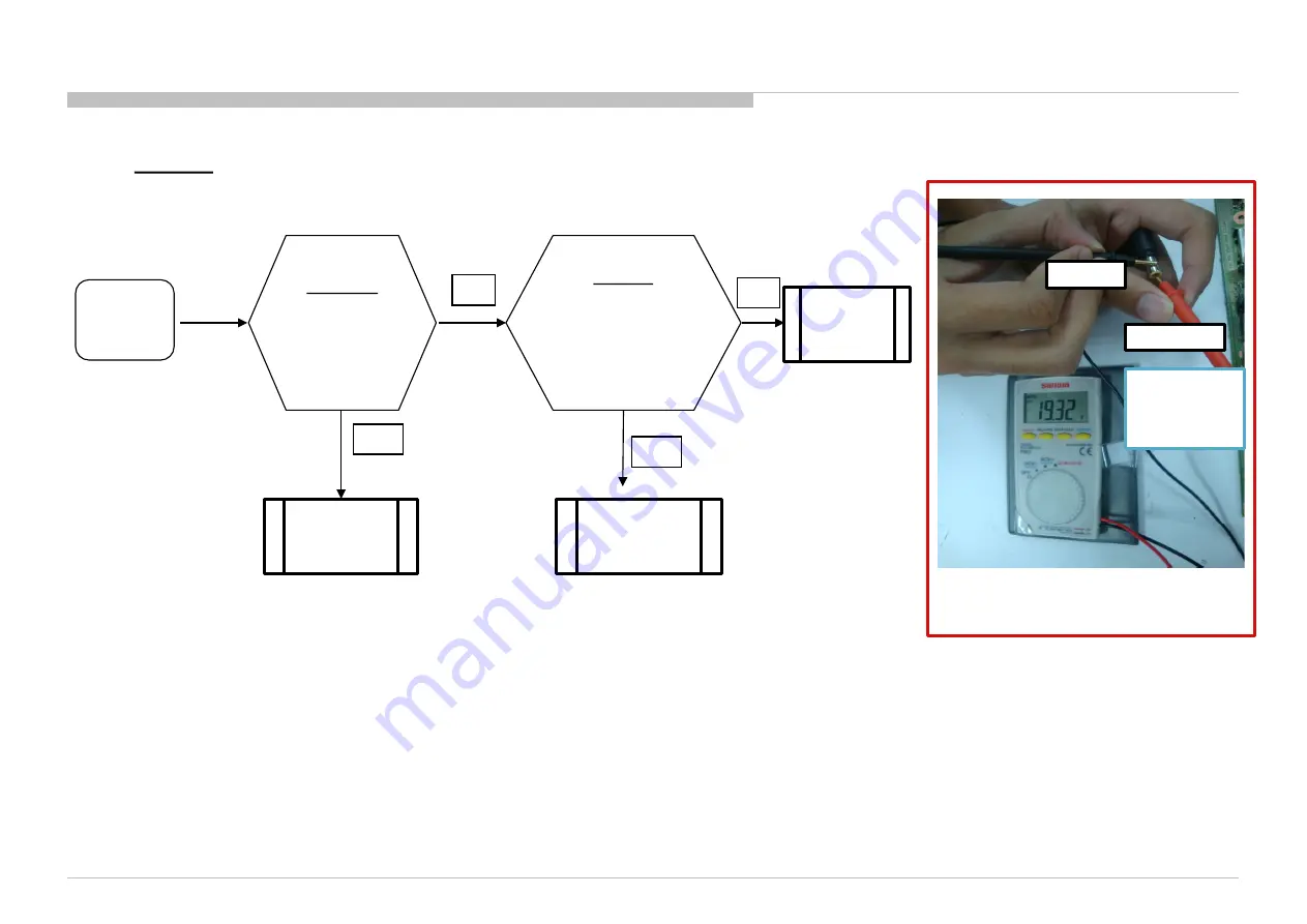
3.2 : 2x Blinking – Main Power Error 

LD Board 

2 times  

Blinking 

Change LD-

Board 

LD-Board 

Check DC voltage at 

Q1002 

18V – 20V? 

*Typical: 19.5V 

Yes 

No 

Change LD-

board 

Change  
Adaptor 

No 

Adaptor 

Take out adaptor  

and check the output voltage. 

 18V – 20V?  

(Refer Figure 1) 

*Typical: 19.5V 

Yes 

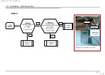
Figure 1: How to check adaptor’s output voltage. 

+ve 

-ve 

Ensure that +ve 

probe is touching 

the needle.  

SYS SET

2018/05/04 04:12:02 (GMT+09:00)

Summary of Contents for KD-43X7 F Series

Page 1: ...t Issue ORIGINAL MANUAL ISSUE DATE 4 2018 GN4UN CHASSIS Segment CHL HISTORY INFORMATION FOR THE FOLLOWING MANUAL LCD TV 9 888 752 01 For SM Unique please refer 9 888 752 Ax America 9 888 752 Ex Europe 9 888 752 Px Asia SYS SET 2018 05 04 04 12 02 GMT 09 00 ...

Page 2: ...SERVICE MANUAL COMMON LCD TV GN4UN CHASSIS Segment CHL SYS SET 2018 05 04 04 12 02 GMT 09 00 ...

Page 3: ...KD 49X7 F KD 55X7 F KD 65X7 F KD 43XF7 KD 49XF7 KD 55XF7 KD 65XF7 MODEL LIST THIS SERVICE MANUAL CONTAINS COMMON INFORMATION FOR BELOW REGIONS AND MODELS REGION ASIA AMERICA EUROPE SYS SET 2018 05 04 04 12 02 GMT 09 00 ...

Page 4: ...ation Exploded Views and Parts List Section Title Page 1 SAFETY NOTES 5 2 SELF DIAGNOSTIC FUNCTION 12 3 TROUBLE SHOOTING 14 4 SERVICE ADJUSTMENTS 115 5 DIAGRAMS 138 4 TABLE OF CONTENTS Note Pictures provided in this Service Manual might have slight difference from the actual sets SYS SET 2018 05 04 04 12 02 GMT 09 00 ...

Page 5: ... service personnel only 2 To reduce the risk of electric shock do not perform any servicing other than that contained in the operating instructions unless you are qualified to do so 3 WARNING An isolation transformer should be used during any service to avoid possible shock hazard because of live chassis The chassis of this receiver is directly connected to the ac power line The replaceable fuse c...

Page 6: ...reen Although the OLED screen is made with high precision technology and 99 99 or more of the pixels are effective black dots may appear or bright points of light white red blue or green may appear constantly on the OLED screen This is a structural property of the OLED screen and is not a malfunction Do not push or scratch the front filter or place objects on top of this TV set The image may be un...

Page 7: ...el refresh will automatically run to adjust the uniformity of the TV screen after it has been in use for long periods of time Panel refresh can also be performed manually and should only be used if image retention is very noticeable or you see the following message Panel refresh did not finish Caution The Panel refresh function may affect the panel As a reference perform the Panel refresh only onc...

Page 8: ...tive earth by diode Leakage current of measurement instrument is less than 10μArms when under test equipment AC plug is opened Set up the following condition and turn on the set Applied voltage Nominal input voltage Description on Nameplate Measure the leakage current between one phase conductor and neutral for terminal A and terminal B Read rms value and then calculate to peak value PEAK VALUE 2 ...

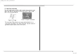
Page 9: ...to guarantee optimal quality of new solder joints 1 7 Lead Free Information The circuit boards used in these models have been processed using Lead Free Solder The boards are identified by the LF logo located close to the board designation Figure 4 LF Logo Figure 5 LF logo on circuit board 9 SYS SET 2018 05 04 04 12 02 GMT 09 00 ...

Page 10: ...1 8 FFC Handling Caution 10 SYS SET 2018 05 04 04 12 02 GMT 09 00 ...

Page 11: ...11 1 9 Solder less Tuner Replacement SYS SET 2018 05 04 04 12 02 GMT 09 00 ...

Page 12: ... be reproduced the remote commander can be used to review the failure occurrence data stored in memory to reveal past problems and how often these problems occur Status LED Colour Remarks Power Off AC Off and 1 OFF 1 power switch off by Side Key Power On White Standby by remote control off and Side Key off OFF Picture Off White Set Sleep Timer Amber Set On Timer Power On Amber Set On Timer Standby...

Page 13: ... Main Board 4 Panel Power Error Main Board 5 Panel I2C Communication Error Main Board or Source Board 6 Backlight Error Main Board Error Detection Symptoms Error Location Tuner Demod Error Cannot tune Digital RF Analog RF Main Board Tuner Module Tuner Demod Error do not go to Safety Shutdown and do not have RED blinking SYS SET 2018 05 04 04 12 02 GMT 09 00 ...

Page 14: ...om 14 Triage Chart SECTION 3 TROUBLESHOOTING Reference Symptoms Shutdown Power LED blinking red diagnostics sequences No Power Video missing or distorted Remote Network Audio Smart Core 2 3 4 5 6 No White Power LED does not reponse to remote Dead Set Stationary colored lines or dots No video One of Inputs No video all Inputs No Remote Wireless can t connect No Audio Smart Core no LED Set is still ...

Page 15: ...TART no Diode D1001 broken 1 Check fuse impedance F1001 Is 1ohm 2 Check impedance D1001 to GND Is 1kohm yes MOSFET Q1007 Broken 3 Check MOSFET Q1007 Is 1kohm no yes MOSFET Q1002 Broken 4 Check MOSFET Q1002 Is 1kohm yes no yes MOSFET Q1008 Broken 5 Check MOSFET Q1008 Is 1kohm 15 SYS SET 2018 05 04 04 12 02 GMT 09 00 ...

Page 16: ...D Check 12 5V_TCON Is voltage 12 0V no yes yes Check TCON_ON C1024 Is voltage 3 0V yes Main device failure no Check MOSFET Q1006 Is 1kohm yes Q1006 broken no Check point on PWB refer next slide START Check fuse F1000 Is 1ohm 12V yes Check Input to GND Is 1k ohm yes DDC IC1000 broken no Check Input to Output Is 1k ohm yes DDC IC1000 broken no Check Output to GND Is 1k ohm yes DDC IC1000 broken no C...

Page 17: ...power LD board F1000 R1003 C1009 C1024 12 5V_TCON Impedance check Q1006 C1016 Output to GND Impedance check Input to GND Impedance check Input to Output Impedance check 17 SYS SET 2018 05 04 04 12 02 GMT 09 00 ...

Page 18: ...3 2 LED Blinking 2x Main power Error Operating Chart BB9 G Board model BB9 AC adapter model 23V 16 44V 12 2V 13 2V 18 SYS SET 2018 05 04 04 12 02 GMT 09 00 ...

Page 19: ... of CN5500 on BB9 Board Voltage 12 2V 13 2V Typical 12 7V Yes No BB9 G Board model BB9 Board G Board 2 time blinking Check 19 5_12 5V_MAIN at pin 15 16 of CN5500 on BB9 Board Voltage 16 44V 23V Typical 19 5V Yes No BB9 AC adapter model BB9 Board LD Board SYS SET 2018 05 04 04 12 02 GMT 09 00 ...

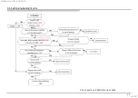
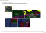
Page 20: ...LD Board Check DC voltage at Q1002 18V 20V Typical 19 5V Yes No Change LD board Change Adaptor No Adaptor Take out adaptor and check the output voltage 18V 20V Refer Figure 1 Typical 19 5V Yes Figure 1 How to check adaptor s output voltage ve ve Ensure that ve probe is touching the needle SYS SET 2018 05 04 04 12 02 GMT 09 00 ...

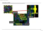
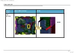
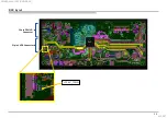
Page 21: ... Supplementary information 21 Check point LD1 Board Name Board PWB A side Detail LD1 Q1002 Q1002 19 5V SYS SET 2018 05 04 04 12 02 GMT 09 00 ...

Page 22: ... Ω Audio IC IC3101 problem Change Speaker Harness Change Main Speaker START Connect back Speaker Connector to CN3109 and perform AC OFF ON DONE 3x blinking No 3x blinking Change B board No connectivity of F3101 Speaker harness shorted 3x blinking F3101 OK Correct Option bit 3x blinking No 3x blinking 3x blinking F3101 OK Check correct Option bit is set Set correct Option bit and perform AC OFF ON ...

Page 23: ...uit damage happen START Audio IC IC3101 problem DONE No 3x blinking 3x blinking and F3101 OK Check have any burn mark on Audio IC If have burn mark replace the NG Audio IC Change B board Check Audio IC pins and surrounding part Replace the NG part if have any For example fuse broken e capacitor blow c capacitor short connection inductor open connection and etc 3x blinking 3x blinking No 3x blinkin...

Page 24: ...B9 CHL Audio Amp circuit Purpose Checking Audio Error pin not short to GND Checking fuse condition Change Audio IC if need Audio IC each pin checking please refer to Audio No Sound B Board Checking Point IC3101 CN3109 F3101 Audio Error pin SYS SET 2018 05 04 04 12 02 GMT 09 00 ...

Page 25: ... Supplementary information 25 3 3 3x Blinking Audio Error Backup Board PWB A side BB9 CHL B Board Checking Point Main IC IC5000 Audio Amp circuit SYS SET 2018 05 04 04 12 02 GMT 09 00 ...

Page 26: ... 5V_TCON 10 8V 13 2V RC ON Suspected LD board G Board side issue Replace PSU unit board TV in standby mode Yes No Replace Main IC B Board Start TV boot up normally No Yes Check Adaptor G board connection CHL 43 49 LD board Adaptor CHL 55 65 G board Adaptor Remove and reinsert Harness from LD board Main board G board Remove and reinsert Harness from Gboard Main board SYS SET 2018 05 04 04 12 02 GMT...

Page 27: ...TV Business Division 27 BB9 layout 51pin LVDS Connector SoC 12 5V_TCON PANEL_PWR 30pin PSU LD Connector SYS SET 2018 05 04 04 12 02 GMT 09 00 ...

Page 28: ...FC is taped properly 5 Times Blinking happen YES No Replace LVDS 51 pin Flat Flexible Cable FFC TV set is OK now NG Symptom Incorrect FFC Insertion 5 Times Blinking happen YES No TV set is OK now NG Symptom LVDS Cable NG Replace B Board 5 Times Blinking happen YES No Replace O Cell or Panel Module Check voltage at 12 5V_TCON Is 10 8 13 2V available YES NO TV set is OK now NG sympton LD board G boa...

Page 29: ...29 BB9 layout 12 5V_TCON 51pin LVDS Connector SoC 30pin PSU LD Connector SYS SET 2018 05 04 04 12 02 GMT 09 00 ...

Page 30: ...30 3 6 6x Blinking backlight error Check point on PWB refer next slide SYS SET 2018 05 04 04 12 02 GMT 09 00 ...

Page 31: ...31 3 6 6x Blinking backlight error SYS SET 2018 05 04 04 12 02 GMT 09 00 ...

Page 32: ...efer 5x Blinking Troubleshooting manual Check Other Portion Tuner No Picture HDMI No Picture Ext Video Input No Picture Yes Replace the V by One FFC Harness LCD Panel T CON NG V by One FFC Harness NG NG OK Replace the main Board Main board NG No NG OK Replace LD G Board NG LD G Board NG OK SYS SET 2018 05 04 04 12 02 GMT 09 00 ...

Page 33: ...and antenna OK Check Tuner power line 3 3V at CL1000 3 3V 1 8V at CL1001 1 8V Tuning for Analog Digital or Satellite Check Tuner power line 12V line at CL1006 12V Satellite Refer Digital Tuning 2 OK For TW DVB AM ATSC LA ISDB EU DVB only Check fuse F1000 continuity Part broken YES Change part F1000 NO Change Tuner Module EU T2S2 SUT CE251ZP Please refer page Assemble and Dissemble Tuner Module Pro...

Page 34: ...ry information 34 Board Name Board PWB A side Detail BB9 board A side 3 3V CL1000 1 8V CL1001 12V CL1006 F1000 BB9 board A side Detail CL1001 1 8V CL1000 3 3V F1000 CL1006 12V SYS SET 2018 05 04 04 12 02 GMT 09 00 ...

Page 35: ...G Analog Tuning NG Noisy Confirm Antenna or Cable connection For LA ISDB PA_ISDB LA T2 For Other destination Channel can be lock Picture quality is noisy Change B board Problem solved OK NG Check part mounting condition for digital control line M_SCL M_SDA OK NG Notes Parts for IFOUTN1 line FB1000 C1005 C1012 Parts for IFOUTP1 line R1030 FB1001 C1006 C1013 Parts for IFAGC1 line C1014 R1010 Parts f...

Page 36: ...36 Board Name Board PWB A side Detail BB9 board A side IFOUTN1 FB1000 C1005 C1012 IFOUTP1 R1030 FB1001 C1006 C1013 FB1000 C1012 C1005 FB1001 C1006 C1013 R1030 SYS SET 2018 05 04 04 12 02 GMT 09 00 ...

Page 37: ...37 Board Name Board PWB A side Detail BB9 board A side IFAGC1 C1014 R1010 R1010 C1014 SYS SET 2018 05 04 04 12 02 GMT 09 00 ...

Page 38: ...38 Board Name Board PWB A side Detail BB9 board A side M SCL C1004 R1049 M SDA C1003 R1048 C1004 R1049 R1048 C1003 SYS SET 2018 05 04 04 12 02 GMT 09 00 ...

Page 39: ... NG Channel can be lock Check part mounting condition for digital control line M_SCL M_SDA NG OK NG OK Change B board Problem solved OK NG Change Tuner Module Please refer page Assemble and Dissemble Tuner Module Check IC 5000 SoC Change B board Change NG parts Problem solved Done End OK Change NG parts NG Notes Parts for IFOUTN1 line FB1000 C1005 C1012 Parts for IFOUTP1 line R1030 FB1001 C1006 C1...

Page 40: ...40 Board Name Board PWB A side Detail BB9 board A side IFOUTN1 FB1000 C1005 C1012 IFOUTP1 R1030 FB1001 C1006 C1013 FB1000 C1012 C1005 FB1001 C1006 C1013 R1030 SYS SET 2018 05 04 04 12 02 GMT 09 00 ...

Page 41: ...Board Name Board PWB A side Detail BB9 board A side IFAGC1 C1014 R1010 R1010 C1014 41 SYS SET 2018 05 04 04 12 02 GMT 09 00 ...

Page 42: ...Board Name Board PWB A side Detail BB9 board A side M SCL C1004 R1049 M SDA C1003 R1048 C1004 R1049 R1048 C1003 42 SYS SET 2018 05 04 04 12 02 GMT 09 00 ...

Page 43: ...n Confirm ANT or Satellite connection For LA T2 For EU T2S2 For EU T2 PA T2 and HK DTMB Channel can be lock OK NG OK NG Check part mounting condition for digital control line M_SDA M_SCL Change B board Problem solved NG OK Change Tuner Module Please refer page Assemble and Dissemble Tuner Module Check IC 5000 SoC Change B board Change NG parts Problem solved Done End Change NG parts OK NG Notes Pa...

Page 44: ...Board Name Board PWB A side Detail BB9 board A side M SCL C1004 R1049 M SDA C1003 R1048 C1004 R1049 R1048 C1003 44 SYS SET 2018 05 04 04 12 02 GMT 09 00 ...

Page 45: ...Board Name Board PWB A side Detail BB9 board A side DEMOD_TSCLK R1020 DEMOD_TSDATA 0 R1019 R020 R1019 45 SYS SET 2018 05 04 04 12 02 GMT 09 00 ...

Page 46: ...riggered Due to region Miss matched EWBS UI ON EWBS Feature is Not Enable During standby NG Tuner power is OFF OK Does any RF signal stored from RF Antenna OK NG Tuner power is OFF Does Tuning RF Antenna OK Refer to 2f 3 1 No Picture Tuner Trouble shooting flow NG Cannot locked any signals EWBS Feature is Not Enable during standby OK END Check mount Part at EWBS line R5066 Replace board NG Part mi...

Page 47: ... Supplementary information 47 3 8 6 NO SOUND No Sound with normal picture Please refer Audio troubleshooting YES NO Only RF tuner input Change B board SYS SET 2018 05 04 04 12 02 GMT 09 00 ...

Page 48: ...up Menu TV turn ON condition START 1 Confirm USB Auto Start is ON or OFF Check 5V at C7012 USB port1 2 Confirm USB file format Change to supported USB format Change to ON Change B Board Main IC IC5000 problem OFF ON END No 5V Do a Factory Setting OK Have 5V but No detection Detection OK OK Picture OK Sound OK OK OK Detection OK and Picture and Sound OK NG OK Audio IC IC3101 problem Sound NG NG USB...

Page 49: ...USB AutoStart at Set up Menu START 1 Confirm USB Auto Start is ON or OFF Check 5V at C7029 USB port2 2 Confirm USB file format Change to supported USB format Change to ON Change B Board Main IC IC5000 problem OFF ON END USB format OK but No detection Do a Factory Setting NG Detection OK Picture OK Sound OK Detection OK and Picture and Sound OK NG OK Audio IC IC3101 problem OK OK OK No 5V Picture N...

Page 50: ...up Menu TV turn ON condition START 1 Confirm USB Auto Start is ON or OFF Check 5V at C7037 USB port3 2 Confirm USB file format Change to supported USB format Change to ON Change B Board Main IC IC5000 problem OFF ON END Do a Factory Setting Detection OK Picture OK Sound OK Detection OK and Picture and Sound OK NG Audio IC IC3101 problem Picture NG OK OK OK OK No 5V NG USB format OK but No detectio...

Page 51: ...rt 1 or 3 Board Name Board PWB A side Detail BB9 3 9 4 USB Port 1 or 3 No Detection Cannot Play No picture No Sound Checking Point USB B board Checking Checking 5V Points USB Port 1 or 3 C7012 C7037 Have 5V SYS SET 2018 05 04 04 12 02 GMT 09 00 ...

Page 52: ...9 5 USB Port 2 Board Name Board PWB A side Detail BB9 3 9 5 USB Port 2 No Detection Cannot Play No picture No Sound Checking Point USB B board Checking Checking 5V Points USB Port 2 C7029 Have 5V SYS SET 2018 05 04 04 12 02 GMT 09 00 ...

Page 53: ...d Check if any abnormal or broken point on Ethernet Connector and parts J7000 L7000 RB7000 C7002 OK Yes No NG Check if TV has good cable connection Set up Network setup Failed OK START END Change a good cable Connector J7000 and parts NG Change B Board T7000 or T7001 or Main IC IC5000 NG Change B Board Failed Check TV has connection OK Set up Network setup OK Failed SYS SET 2018 05 04 04 12 02 GMT...

Page 54: ...PWB A side Detail BB9 Ethernet B board Checking Checking parts broken or knock off T7000 J7000 Check any parts broken or knock off T7001 L7000 RB7000 C7002 3 10 Ethernet No Connect General Checking SYS SET 2018 05 04 04 12 02 GMT 09 00 ...

Page 55: ...Channel Setup Digital Setup CA Module Yes Yes No Insert CICAM and Check CI 5V at PIN 17 18 51 52 3 Check Resistor Part mounting 2 Insert CICAM and Check CI Detection at Pin 36 67 No Yes No Yes No NG Yes Check CI or CI case CI CI Check service menu for CI Credentials CI Key Valid key Invalid key Invalid Key Change B Board IC7003 NG Change B Board Picture and Sound OK Main IC IC5000 NG Change B Boar...

Page 56: ...lot Board Name Board PWB A side Detail BB9 3 11 CI Slot Cannot Play No picture No Sound Checking Point CI Slot B board Checking Checking 5V Points 1 3 CI 5V at PIN 17 18 51 52 SYS SET 2018 05 04 04 12 02 GMT 09 00 ...

Page 57: ...re No Sound Checking Point CI Slot B board Checking Checking CI Detection Pin Points 2 3 Board Name Board PWB A side Detail BB9 Card Detect 1 PIN 36 Card Detect 2 PIN 67 Remark Both CI Detection Pin should be 3 3V before CICAM insert and 0v when CICAM inserted SYS SET 2018 05 04 04 12 02 GMT 09 00 ...

Page 58: ...ing Point CI Slot B board Checking Checking Resistor Part Mounting Points 3 3 Board Name Board PWB A side Detail BB9 Ref No Location Ref No Location RB7003 1 RB7012 6 RB7004 2 RB7020 7 RB7005 3 RB7010 4 Remark Confirm these 6 resistors part are mount properly or not 6 5 4 3 2 1 SYS SET 2018 05 04 04 12 02 GMT 09 00 ...

Page 59: ...ssue Title 3 No Picture Symptom 1 No Red LED Blinking 2 White LED 3 12 HDMI No Picture 3 12 1 HDCP Failure Analysis 3 12 2 5V Power Failure Analysis 3 12 3 HPD Failure Analysis 3 12 4 I2C Failure Analysis 3 12 5 TMDS Failure Analysis 3 12 6 Bravia Sync CEC not function HDMI SYS SET 2018 05 04 04 12 02 GMT 09 00 ...

Page 60: ...place Re verify NG Connector abnormal OK Picture recovered Check voltage of 5V Power HDMI1 CN4001 Pin 18 HDMI2 CN4002 Pin 18 HDMI3 CN4000 Pin 18 OK Appearance OK Go to 5V Power Failure Analysis Page NG V5V 4 8 5 3V NG No picture Check voltage of HPD HDMI1 CN4001 Pin 19 HDMI2 CN4002 Pin 19 HDMI3 CN4000 Pin 19 OK V5V 4 8 5 3V Go to HPD Power Failure Analysis Page NG VHPD 2 4 5 3V OK VHPD 2 4 5 3V Co...

Page 61: ...in 15 16 HDMI3 CN4000 Pin 15 16 Go to I2C Failure Analysis Page NG VI2C 3 5 5 5V OK VI2C 3 5 5 5V Check voltage of TMDS line HDMI1 CN4001 Pin1 3 4 6 7 9 10 12 HDMI2 CN4002 Pin1 3 4 6 7 9 10 12 HDMI3 CN4000 Pin1 3 4 6 7 9 10 12 NG VTMDS 2 6 3 5V Go to TMDS Failure Analysis Page OK VTMDS 2 6 3 5V Replace B board re verify Escalate this issue to R D team END 3 12 HDMI No picture General Checking Cont...

Page 62: ...MI Verify HDMI Source device compatibilities for HDCP version 1 4 Replace B Board and Re verify HDCP key corrupted Escalate this issue to R D team NG No picture END HDCP Failure Analysis Verify HDMI Source device compatibilities for HDCP version 2 2 OK Compatible NG Not Compatible HDMI Source incompatible for HDCP1 4 and HDCP 2 2 OK Picture recovered OK Compatible NG Not Compatible HDCP2 2 Issues ...

Page 63: ... HDMI 5V Power Failure Analysis Check impedance of Varistor during AC OFF HDMI1 VR4010 HDMI3 VR4009 OK Impedance 100kΩ 5 NG Impedance 100kΩ 5 END Go to HPD Power Failure Analysis Page Replace Broken Varistor and Re verify OK Picture recovered NG No picture Check impedance of Resistor during AC OFF HDMI1 R4025 HDMI3 R4024 NG Impedance 1K Ω OK Impedance 1K Ω Replace Broken Resistor and Re verify NG ...

Page 64: ...n HDMI 5V Power Failure Analysis Check impedance of Varistor during AC OFF HDMI2 VR4011 OK Impedance Open High Z NG Impedance Open High Z END Go to HPD Power Failure Analysis Page Replace Broken Varistor and Re verify OK Picture recovered NG No picture Check impedance of Resistor during AC OFF HDMI2 R4044 NG Impedance 22 Ω OK Impedance 22 Ω Replace Broken Resistor and Re verify NG No picture OK Pi...

Page 65: ...ance of Resistor during AC OFF HDMI1 R4016 R4019 and R4022 HDMI3 R4015 R4018 and R4021 NG Any of the part as below R4021 R4022 4 7KΩ R4015 R4016 R4018 R4019 1KΩ OK All part as below R4021 R4022 4 7KΩ R4015 R4016 R4018 R4019 1KΩ Check HPD GPIO Line impedance to Ground during AC OFF HDMI1 R4019 HDMI3 R4018 Replace B Board and Re Verify Internal Main IC SoC Broken IC5000 Go to I2C Failure Analysis Pa...

Page 66: ...sis END Replace Broken Resistor and Re verify OK Picture recovered Check impedance of Resistor during AC OFF HDMI2 R4043 NG Resistance 4 7 Ω OK Resistance 4 7 Ω Check HPD GPIO Line impedance to Ground during AC OFF HDMI2 R4043 Replace B Board and Re Verify Internal Main IC SoC Broken IC5000 Go to I2C Failure Analysis Page NG No Picture Please refer page 67 for actual measuring points OK Impedance ...

Page 67: ...2 3 HPD Failure Analysis Measuring point for HPD GPIO line references to ground R4018 Only measure this point reference to GND R4019 Only measure this point reference to GND HDMI3 HDMI1 HDMI2 R4043 Only measure this point reference to GND SYS SET 2018 05 04 04 12 02 GMT 09 00 ...

Page 68: ...edance of Resistor during AC OFF HDMI1 RB4001 HDMI2 RB4002 HDMI3 RB4000 Check I2C GPIO Line impedance to Ground during AC OFF HDMI1 CN4001 Pin15 16 HDMI2 CN4002 Pin15 16 HDMI3 CN4000 Pin15 16 Replace B Board and Re Verify Internal Main IC SoC Broken IC5000 Go to TMDS Failure Analysis Page OK Impedance 47kΩ NG No Picture NG Impedance 47kΩ OK HDMI1 Impedance 140kΩ 5 OK HDMI2 Impedance Open High Z OK...

Page 69: ... Picture recovered Check impedance of Resistor CMF Filter during AC OFF HDMI1 RB4007 RB4008 L4002 L4003 HDMI2 RB4003 RB4004 L4004 L4005 HDMI3 RB4005 RB4006 L4000 L4001 Check I2C GPIO Line impedance to Ground during AC OFF HDMI1 CN4001 Pin1 3 4 6 7 9 10 12 HDMI2 CN4002 Pin1 3 4 6 7 9 10 12 HDMI3 CN4000 Pin1 3 4 6 7 9 10 12 Replace B Board and Re Verify NG Impedance Open High Z OK Impedance Open Hig...

Page 70: ...C TV setting NG CEC setting Off OK CEC Setting On Factory Reset Change Proven OK HDMI cable Physical appearance Check On HDMI connector NG Connector abnormal NG CEC not functioning HDMI Connector Broken Replace Re verify Turn TV Bravia Sync Check impedance Of R4015 Resistor during AC OFF OK Connector no abnormality Resistor Broken Replace Re verify NG R4031 100Ω OK CEC functioning Replace B Board ...

Page 71: ...ure Checking Point Pin 19 Pin 1 Zoom 1 Zoom 2 Zoom 4 Zoom 3 R4019 R4016 RB4001 VR4010 L4003 L4002 Zoom 1 HDMI1 CN4001 Zoom 2 HDMI2 Pin 1 Pin 19 L4004 L4005 RB4002 VR4011 More on the next slide CN4002 R4007 R4004 R4005 R4008 R4022 R4025 R4044 R4043 SYS SET 2018 05 04 04 12 02 GMT 09 00 ...

Page 72: ...I No Picture HDMI No picture Checking point continued R4031 Zoom 4 Zoom 3 RB4003 RB4004 RB4006 RB4005 Zoom 4 RB4007 Zoom 3 HDMI3 Pin 1 Pin 19 L4000 L4001 RB4000 VR4009 RB4008 CN4000 R4015 R4018 R4021 R4036 R4003 R4006 R4024 SYS SET 2018 05 04 04 12 02 GMT 09 00 ...

Page 73: ... RB4001 RB4002 1 257 548 21 RES NETWORK 47K 1005X4 4 R4043 1 220 803 81 RES CHIP 4 7 1005 5 R4044 1 218 933 81 RES CHIP 22 1005 6 R4003 R4004 R4005 R4006 R4007 R4008 R4031 1 218 941 81 RES CHIP 100 1005 7 R4036 1 218 944 81 RES CHIP 180 1005 8 R4015 R4016 1 218 953 81 RES CHIP 1 0K 1005 9 R4018 R4019 R4024 R4025 1 250 495 11 RES METAL FILM CHIP 1 0K 1005 10 R4021 R4022 1 218 961 81 RES CHIP 4 7K 1...

Page 74: ...ble NG WiFi Direct Off OK Check STBY_5V IC6016 OK NG DC Voltage not 5V Check Harness Connection CN9500 Harness not in Good Condition Change Harness NG Harness Connection Not Ok DDCON IC6016 Broken Change B Board Check TP VCC DNUR SY3 NG DC Voltage is not 5V WiFi Module DNUR SY3 Broken Change WiFi Module OK Check AP Device OK NG Signal Strength Low AP Device Problem Change AP Device OK END Connecti...

Page 75: ...75 75 3 13 WIFI Board Name Board PWB A side Detail BB9 IC6016 IC6016 IC6016 3 13 WIFI Cannot search device Connection Failed Checking Point SYS SET 2018 05 04 04 12 02 GMT 09 00 ...

Page 76: ...76 3 13 WIFI 3 13 WIFI Cannot search device Connection Failed Checking Point SYS SET 2018 05 04 04 12 02 GMT 09 00 ...

Page 77: ... IC troubleshooting manual J2002 Connectivity Problem Parts Broken Change Part J2002 Connector Problem Change connector Yes No Yes No Check all parts at CVBS0P signal path VR2000 R2004 C2000 R2017 Check R2021 voltage Is it 3 3V No Yes Yes No Video No Picture 3 14 1 Video Analog Signal Path No Picture General Checking WW Destination BB9 SYS SET 2018 05 04 04 12 02 GMT 09 00 ...

Page 78: ...icture WW Destination 3 14 1 Video Analog Signal Path No Picture Checking Point WW Destination BB9 Board Name Board PWB A side Details BB9 WW J2002 VR2000 R2021 R2004 C2000 BB9 WW C2006 R2017 Details Details J2002 R2021 VR2000 C2000 R2004 R2017 C2006 SYS SET 2018 05 04 04 12 02 GMT 09 00 ...

Page 79: ...o Check all parts at CVBS0P signal path VR2000 R2004 C2000 R2017 Parts Broken Change Part No IC5000 Problem Refer IC troubleshooting manual Video No Picture J2000 connector Problem Change connector Yes No Parts Broken Change Part No IC5000 Problem Refer IC troubleshooting manual Component No Picture Check Vpp waveform at 1 C2003 for Y 1V 2 C2008 for Pb 0 7V 3 C2009 for Pr 0 7V Check all parts Y VR...

Page 80: ... R2004 R2005 R2006 C2000 C2001 C2002 VR2000 VR2001 VR2002 BB9 UC C2003 C2006 C2008 C2009 R2014 R2017 R2018 R2019 This image cannot currently be displayed This image cannot currently be displayed Details J2000 Details This image cannot currently be displayed This image cannot currently be displayed R2004 R2014 R2018 R2019 R2017 C2003 C2006 C2008 C2009 R2005 R2006 C2000 C2001 C2002 VR2000 VR2001 VR2...

Page 81: ... Q6007 pin1 Q6007 pin3 IC6010 3 3V_DDC_OUT STBY F6005 R6089 C6093 C6086 3 3V_Main Q6008 pin2 Q6009 pin1 Q6009 pin3 IC6007 1 8V_TU R6162 C6058 C6055 IC6017 1 0V_M3 F6006 R6114 C6146 C6106 IC6004 1 5V_DDR C6153 C6042 C6040 IC6014 1 05V_M3_A R6120 C6134 C6130 IC6016 5V_WIFI R6167 C6141 C6136 LDO IC6018 1 8V_EMMC IC Pin3 C6125 C6124 IC6005 1 05V_STBY IC Pin3 C6050 C6049 SYS SET 2018 05 04 04 12 02 GMT...

Page 82: ...on TV Business Division 82 Block Diagram B Board Adaptor PSU LD G Board 3 3V DDC 5 0V DDC 1 0V DDC 1 8V DDC TUNER 1 5V DDC 1 05V DDC 5V DDC WIFI 1 8V LDO 1 05V LDO 43 49 55 65 19 5V 12 7V SYS SET 2018 05 04 04 12 02 GMT 09 00 ...

Page 83: ...D DDCON LDO working normal no yes no yes no yes no yes Check C6134 C6050 is it 1 05V yes no Check C6058 is it 1 8V yes no Check 3 3V_MAIN C6130 Voltage Is the voltage 3 3V DDC 3 3V_DDC_OUT check DDC 1 5V_DDR check DDC 5 0V_DDC_OUT check DDC 5V_WIFI check LDO 1 05V_M3_xx check DDC 1 8V_TU check SW 3 3V_MAIN check Check C6146 Voltage Is the voltage 1V no yes DDC 1 0V_M3 check yes no Check C6125 is i...

Page 84: ...Vcc C6082 voltage Is voltage 5 3V Check fuse F6005 Is fuse OK Change IC6010 Change F6005 no yes no no yes yes END G Board LD Board Check input F6005 voltage Is voltage 19 0V G Board model Check input F6005 voltage Is voltage 12 0V yes yes yes no no LD Board model CHL 55 65 G Board model PSU CHL43 49 LD Board model ADP SYS SET 2018 05 04 04 12 02 GMT 09 00 ...

Page 85: ...TART yes Change DDCON IC6004 Check Vcc voltage C6040 Is voltage 3 3V yes Check D6001 Is diode ok no yes Check 3 3V_STBY G board or IC6010 Change D6002 no Check Vcc voltage C6040 Is voltage 5V yes Check D6002 Is diode ok no yes Check 5V_MAIN DDCON IC6009 Check IC6009 Vcc voltage C6066 Is voltage 19 5V no Is IC6004 mounted yes no yes SYS SET 2018 05 04 04 12 02 GMT 09 00 ...

Page 86: ...s Division 86 3 15 No Power DDCON LDO SW 5V_MAIN check Check VG signal Q6007 pin1 Is voltage 4 9V Change Q6006 no yes Other Issue START Change Q6007 Check VB signal Q6006 pin2 Is voltage 1 9V yes no 86 SYS SET 2018 05 04 04 12 02 GMT 09 00 ...

Page 87: ... voltage Is voltage 5V Check fuse F6004 Is fuse OK Change IC6009 Change F6004 no yes no no yes yes END yes Check input F6004 voltage Is voltage 19 0V LD Board model G Board model Check input F6004 voltage Is voltage 12 0V yes yes no no G Board LD Board G Board LD Board CHL 55 65 G Board model PSU CHL 43 49 LD Board model ADP 87 SYS SET 2018 05 04 04 12 02 GMT 09 00 ...

Page 88: ... Is voltage 5 3V MTK IC damage Change IC6017 Change F6006 no yes no no yes END START yes yes Check input F6006 voltage Is voltage 19 0V LD Board model G Board model Check input F6006 voltage Is voltage 12 0V yes yes no no Check fuse F6006 Is fuse OK G Board LD Board CHL 55 65 G Board model PSU CHL43 49 LD Board model ADP 88 SYS SET 2018 05 04 04 12 02 GMT 09 00 ...

Page 89: ...05 pin3 Is voltage 3 0V START Check input C6049 voltage Is voltage 3 0V DDC 3 3V_DDC_OUT check no yes yes DDC 3 3V Switching check no yes Change IC6018 Check EN signal IC6018 pin3 Is voltage 3 0V START Check input C6124 voltage Is voltage 3 0V DDC 3 3V Switching check no yes yes 1 05V_M3_STBY 1 8V_EMMC LDO 1 8V_EMMC 89 SYS SET 2018 05 04 04 12 02 GMT 09 00 ...

Page 90: ... 8V_TU check no yes Change IC6007 START Check voltage C6055 Is voltage 5 0V Check EN signal R6162 Is voltage 1 6V yes no Check D6011 Is diode ok no Change D6011 yes Check 5 0V_DDC_OUT Check D6009 Is diode ok Change D6009 MTK IC damage no yes 90 SYS SET 2018 05 04 04 12 02 GMT 09 00 ...

Page 91: ...n 91 3 15 No Power DDCON LDO DDC 1 05V_M3_A check no yes Change IC6014 START Check voltage C6130 Is voltage 3 0V Check EN signal R6120 Is voltage 3 0V yes no DDC 3 3V switching check DDC 3 3V switching check 91 SYS SET 2018 05 04 04 12 02 GMT 09 00 ...

Page 92: ...on 92 3 15 No Power DDCON LDO DDC 5 0V_WIFI check no yes Change IC6016 START Check voltage C6136 Is voltage 3 0V Check EN signal R6167 Is voltage 3 0V yes no MTK IC damage Check 3 3V_STBY G board or IC6010 92 SYS SET 2018 05 04 04 12 02 GMT 09 00 ...

Page 93: ... Division 93 3 15 No Power DDCON LDO SW 3 3V_MAIN check Check VG signal Q6009 pin1 Is voltage 3 0V Change Q6008 no yes Other Issue START Change Q6009 Check VB signal Q6008 pin2 Is voltage 1 9V yes no 93 SYS SET 2018 05 04 04 12 02 GMT 09 00 ...

Page 94: ...ntary information TV Business Division 94 3 15 No Power DDCON LDO DDC LDO Locations IC6005 IC6004 IC6017 Q6006 Q6007 IC6016 IC6007 Q6008 Q6009 IC6009 IC6010 IC6018 IC6014 94 SYS SET 2018 05 04 04 12 02 GMT 09 00 ...

Page 95: ...TV Business Division 95 3 15 No Power DDCON LDO DDC LDO Locations DDC 3 3V_DDC_OUT DDC 1 5V_DDR DDC 5 0V_DDC_OUT C6086 F6005 C6093 IC6010 IC6009 F6004 C6072 C6066 C6153 C6042 IC6004 C6040 95 SYS SET 2018 05 04 04 12 02 GMT 09 00 ...

Page 96: ...on TV Business Division 96 3 15 No Power DDCON LDO DDC LDO Locations DDC 5V_WIFI DDC 1 0V_M3 DDC 1 8V_TU C6106 F6006 R6114 IC6017 C6146 R6167 C6141 C6136 IC6016 C6058 IC6007 R6162 C6055 96 SYS SET 2018 05 04 04 12 02 GMT 09 00 ...

Page 97: ...TV Business Division 97 3 15 No Power DDCON LDO DDC LDO Locations DDC 3 3V_MAIN DDC 5V_MAIN DDC 1 05V_M3_A Q6009 Q6008 PIN1 VG PIN2 VB Q6007 Q6006 PIN2 VB PIN1 VG C6130 R6120 C6134 IC6014 97 SYS SET 2018 05 04 04 12 02 GMT 09 00 ...

Page 98: ...lementary information TV Business Division 98 3 15 No Power DDCON LDO DDC LDO Locations DDC 1 05V_STBY DDC 1 80V_EMMC IC6005 PIN3 C6050 C6049 C6125 C6124 PIN3 IC6018 98 SYS SET 2018 05 04 04 12 02 GMT 09 00 ...

Page 99: ...tail Audio Problem 3 16 2 1 Main Speaker No Sound 3 16 2 2 Headphone HP Out No Sound 3 16 2 3 Analog Audio Input No Sound 3 16 2 4 Analog RF No Sound 3 16 2 5 HDMI Audio No Sound 3 16 2 6 HDMI ARC Failure 3 16 2 7 USB Audio No Sound 3 16 2 7 1 USB Port1 No Detection Cannot Play No Picture No Sound 3 16 2 7 2 USB Port2 No Detection Cannot Play No Picture No Sound 99 SYS SET 2018 05 04 04 12 02 GMT ...

Page 100: ...DD 3 3V 3 3V 10 AVSS 0V 0V 11 AVCC 3 3V 3 3V 12 GVDD 5V 5V 13 VR_ANA 5V 5V 14 BSTPR 14 7Vrms 11 4Vrms Label Name AC Adapter PSU board Common Voltage Voltage Frequency 15 VOUTPR 9 7Vrms 6 4Vrms 384kHz 16 PVDDR 19 5V 12 7V 17 VOUTNR 9 7Vrms 6 4Vrms 384kHz 18 BSTNR 14 7Vrms 11 4Vrms 19 BSTNL 14 7Vrms 11 4Vrms 20 VOUTNL 9 7Vrms 6 4Vrms 384kHz 21 PVDDL 19 5V 12 7V 22 VOUTPL 9 7Vrms 6 4Vrms 384kHz 23 BS...

Page 101: ... 3 16 1 Audio D Amp IC Normal Operation Condition 3 16 1 Audio D Amp IC Normal Operation Condition 1 2 19 5V 12 7V 3 4 5 6 7 10 26 9 13 11 12 8 27 25 24 23 22 21 20 17 18 19 16 B board Zoom F3101 IC3101 28 15 14 101 SYS SET 2018 05 04 04 12 02 GMT 09 00 ...

Page 102: ...aker No Sound Headphone HP Out No Sound Video Component No Sound Analog RF No Sound HDMI Audio No Sound USB Audio No Sound Refer Main Speaker No Sound Refer HP Out No Sound Refer Analog Audio Input No Sound Refer Analog RF No Sound Refer HDMI Audio No Sound Refer USB Audio No Sound HDMI ARC Failure Refer HDMI ARC Failure 102 SYS SET 2018 05 04 04 12 02 GMT 09 00 ...

Page 103: ...C5000 or Audio IC IC3101 problem No connectivity for speaker harness No Sound No Sound Sound Sound No connectivity of F3101 No Sound No Sound Change Speaker Harness Change Main Speaker F3101 broken Replace F3101 Sound No Sound F3101 OK Sound No Sound F3101 OK Do a Factory Setting set to desire channel with sound No Sound Check I2S lines short to GND BCLK LRCLK SDATA0 Any I2S line short to GND No S...

Page 104: ...pplementary information TV Business Division 104 3 16 2 Troubleshooting Detail Audio Problem 3 16 2 1 Main Speaker No Sound IC5000 SDATA0 BCLK LRCLK IC5000 B board 104 SYS SET 2018 05 04 04 12 02 GMT 09 00 ...

Page 105: ... Headphone Headphone problem No Sound Headphone OK Sound No Sound Check AV Setup Headphone is selected No Sound Do a Factory Setting set to desire channel with sound Headphone Inserted Check J3501 Pin4 Voltage Replace J3501 No Sound Headphone OK J3501 Pin4 is 3 3V No Sound Headphone OK J3501 Pin4 is 3 3V No Sound Headphone OK J3501 Pin4 is 0V No Sound Sound Sound Sound 105 SYS SET 2018 05 04 04 12...

Page 106: ...upplementary information TV Business Division 106 3 16 2 Troubleshooting Detail Audio Problem 3 16 2 2 Headphone HP Out No Sound J3501 IC3501 Pin4 IC5000 B board 106 SYS SET 2018 05 04 04 12 02 GMT 09 00 ...

Page 107: ...ound Check Analog Input Source use another input source Analog Input Source problem Refer Audio Problem Speaker No Sound HP No Sound Sound Check correct Source mode is selected No Sound No Sound No Sound RCA cable OK No Sound Analog Input Source OK Sound Speaker Headphone OK Sound Sound No Sound Do a Factory Setting set to desire channel with sound Check Speaker Headphone Using other input mode 10...

Page 108: ...ble OK RF source OK Change RF cable Change RF source channel Refer Main Speaker No Sound Tuning OK Refer Tuner Problem Correct UI setting NG OK NG OK NG NG OK OK START DONE Change B board NG OK No Sound No Sound Sound Sound Sound No Sound Do a Factory Setting complete the RF tuning UI setting OK TV System AFT Audio Filter No Sound No Sound UI OK No Sound Sound 108 SYS SET 2018 05 04 04 12 02 GMT 0...

Page 109: ...ge HDMI cable Change HDMI source channel HDMI Playback OK Refer HDMI Problem NG OK NG OK NG OK START DONE Change B board No Sound No Sound Sound Sound Do a Factory Setting set to desire HDMI source with sound No Sound No Sound Correct UI setting NG UI setting OK TV System settings UI OK No Sound No Sound Sound Sound 109 SYS SET 2018 05 04 04 12 02 GMT 09 00 ...

Page 110: ...ly Bravia Sync CEC TV setting NG CEC setting Off OK CEC Setting On Factory Reset Change Proven OK HDMI cable Physical appearance Check On HDMI connector NG Connector abnormal NG ARC not functioning HDMI Connector Broken Replace Re verify OK Connector no abnormality Resistor Broken Replace Re verify NG R4036 180Ω OK ARC functioning Replace B Board And Re verify END OK R4036 180Ω 5 NG ARC not functi...

Page 111: ...ision 111 3 16 2 Troubleshooting Detail Audio Problem 3 16 2 6 HDMI ARC Failure HDMI 2 CN4002 HDMI 3 CN4000 Zoo m Pin 19 Pin 1 R4036 No Ref No Part No Description 1 R4036 1 218 944 81 RES CHIP 180 1005 111 SYS SET 2018 05 04 04 12 02 GMT 09 00 ...

Page 112: ...deo USB device OK USB source OK Change USB device Change USB source channel USB Playback OK Refer USB Problem Correct UI setting NG OK NG OK NG OK START DONE Change B board NG UI OK No Sound No Sound Sound Sound Sound No Sound Do a Factory Setting set to desire USB file with sound No Sound No Sound Sound 112 SYS SET 2018 05 04 04 12 02 GMT 09 00 ...

Page 113: ...AutoStart at Set up Menu TV turn ON condition START 1 Confirm USB Auto Start is ON or OFF Check 5V at C7012 USB port1 2 Confirm USB file format Change to supported USB format Change to ON Change B Board Main IC IC5000 problem OFF ON END No 5V Do a Factory Setting OK Have 5V but No detection Detection OK OK Picture OK Sound OK OK OK Detection OK and Picture and Sound OK NG OK Audio IC IC3101 proble...

Page 114: ...AutoStart at Set up Menu TV turn ON condition START 1 Confirm USB Auto Start is ON or OFF Check 5V at C7029 USB port2 2 Confirm USB file format Change to supported USB format Change to ON Change B Board Main IC IC5000 problem OFF ON END USB format OK but No detection Do a Factory Setting NG Detection OK Picture OK Sound OK Detection OK and Picture and Sound OK NG OK Audio IC IC3101 problem OK OK O...

Page 115: ... item Confirm the change Return Previous page Cursor Left Right Up Down Change focus item Change option of focus item Return to previous page Return Return to previous page close service menu Note 1 For changes made to Service Mode items to take effect i AC Off On 2 To completely exit Service Mode i RC Off On ii AC Off On These items availability depend on TV region Items Region s Available Wide B...

Page 116: ...Only available if Wi Fi set to on 2 Press Enter or Return button to return to Service Mode Main Micro SW Version NVM Version Boot Version Panel ID Version Wi Fi Version PQ Version AQ Version vX XXX TD1 000 vX XX PA0 XXX JEDI L0 MP1 mt7603u vX X PQ0 XXX AQ0 XXXX SYS SET 2018 05 04 04 12 02 GMT 09 00 ...

Page 117: ...f diagnosis history press Enter or button to enter Self Check 2 Press Enter button to back to Service Mode Home Exit Service Mode Tu Data for Serv 1_IS6S320CNO0101 30 123475 BCD 9876543 Off Factory SERIAL NUMBER EDIT Model Number Setting TEST RESET UART Selection HDD Performance Check AAA Status Information Self diagnosis history Panel Selection STATUS 1st Tu Infor LVDS Spectrum SELF CHECK Back Ho...

Page 118: ...ion Time h max 65535 max 65535 max 65535 0 indicates no error detected 1 indicates an error detected Error count Error name Total Operation Time and Panel Operation Time is recorded every 1h Numbers of Standby LED flash TU_DEMOD do not have standby LED flash Entry 1 Go to Standby by pressing the power button of remote power key 2 Push the buttons sequentially Display 5 Vol Power Exit Power off on ...

Page 119: ...Times Monitoring Items Content 2 REG19 5V_MON REG 19 5V Failure 3 X_AUDIO_MON Audio Failure 3 AUDIO_I2C M_SDA1 SCL1 Audio I2C communication failure 4 PANEL12V_MON Panel 12V Failure 5 PANEL I2C ACK Panel ID NVM Failure 6 BL_ERR Backlight Error SYS SET 2018 05 04 04 12 02 GMT 09 00 ...

Page 120: ...onfirm if Panel Selection and LVDS Spectrum values are correct Model Panel Selection LVDS spectrum KC CHL 43 13_YS7S430HNG0101_4 3 KC CHL 49 14_YS7S490HNG0101_4 3 KC CHL 4K Panel Less 1_PNLLESS_4KMTFY17_0 0 KC CHL 55 16_YS7W550HND0101_4 3 KC CHL 65 17_YS7W650HNU0101_4 3 SYS SET 2018 05 04 04 12 02 GMT 09 00 ...

Page 121: ...ness Division 121 4 7 Serial Number Edit 121 1 Press button to enter edit mode for Serial Number 2 Press Up or Down button to change number and button to edit next number SYS SET 2018 05 04 04 12 02 GMT 09 00 ...

Page 122: ...rrect Select NO if input data is incorrect Press Enter to save answer 4 If YES is selected the input data is saved into EEPROM SERIAL NUMBER EDIT is greyed out and the serial number that has been input is displayed User will not able to select SERIAL NUMBER EDIT to edit anymore The font color of YES is change to black when it is selected 122 SYS SET 2018 05 04 04 12 02 GMT 09 00 ...

Page 123: ...ed into EEPROM The serial number that has been input is displayed User still can edit the Serial Number The font color of NO is change to black when it is selected Step i Enter Self diagnosis history Self Check ii Press 6 0 Warning please don t reset the serial number unnecessarily Always check the input data is correct before rewrite When data is clear it affect both Model number serial number SY...

Page 124: ...siness Division 4 8 Model Number Setting 124 1 Press button to enter edit mode for Model Number 2 Press Up or Down button to select character and to edit next character SYS SET 2018 05 04 04 12 02 GMT 09 00 ...

Page 125: ...orm user to confirm data Press or button to select YES or NO Select YES if input data is correct Select NO if input data is incorrect Press Enter to save answer 4 If YES is selected the input data is saved into EEPROM Model Name EDIT is greyed out and the model name that has been input is displayed User will not able to edit anymore The font color of YES is change to black when it is selected SYS ...

Page 126: ...elected Model Number clear Model Number can be set 5 times only After limit 5 times Model Number cannot be clear will keep the last Serial Number Step i Enter Self diagnosis history Self Check ii Press 6 0 Warning please don t reset the serial number unnecessarily Always check the input data is correct before rewrite When data is clear it affect both Model number serial number 126 SYS SET 2018 05 ...

Page 127: ...lt Value 512 Range 0 1023 2 Start WB adjustment by changing R G B Gain Offset register Remark 1 Whenever these R G B Gain R G B Offset values have been set these values will be applied common to all Picture Mode Vivid Standard Custom Color Temperature Cool Neutral Warm Expert1 Expert2 After operation is completed just exit the Service Menu page Remark 2 To set these R G B Gain R G B Offset values ...

Page 128: ...ransf by pressing or on remote commander b To change the items press or on remote commander and press Enter button select 1 T con to SoC for each items c Select start and press Enter button to start transfer Remark 1 AC OFF ON TV is required for the data to be reflected and updated into the TV s NVM 1 T con to SoC 1 T con to SoC 1 T con to SoC 128 SYS SET 2018 05 04 04 12 02 GMT 09 00 ...

Page 129: ...lect OFF Exit Service Mode by pressing Return on Remote Commander Remark 2 Ensure that there is no Cable RF HDMI etc connected to the TV Test Reset Press Power tact key on TV with keep pressing Up key on RC Then displays RESET on Screen Remark 3 Perform Test Reset on TV after turning OFF Aging Mode 129 SYS SET 2018 05 04 04 12 02 GMT 09 00 ...

Page 130: ...4 11 Tuner Detection 1 Press Enter or button to enter Tuner Detection 2 Go to Back and press Enter or button to return to Service Mode 130 SYS SET 2018 05 04 04 12 02 GMT 09 00 ...

Page 131: ...uner module is not inserted correctly Tuner Status Wrong Region Wrong tuner module is inserted Tuner Status will only update if Tuner Check On and AC Off On is already performed 5 Expected Tuner Type is the expected tuner module to be inserted to TV 6 Mounted Tuner Type is the type of tuner module that is currently inserted to TV Tuner Type Tuner Module region 0 AEP T2S2 1Tuner 2 AEP T2 3 TW DVB 1...

Page 132: ...onnected to an amplifier that support ARC and set Atmos EDID even when amplifier doesn t support Atmos ATMOS_CEC_DISABLE EEPROM 0x30A0 Data 0 A Default 0 Purpose Data A is able to skip Atmos judgment CEC Report Short Audio Descriptor that comes from the amplifier and set Atmos EDID as the service c m to an amplifier that supports Atmos but it reply NO Atmos Remarks 1 This data is not changed by so...

Page 133: ...Default 0 Purpose To avoid CEC conflict for Non CEC compliant device Usage When market claim happen such as Bravia Sync malfunction or no ARC sound happen due to HDMI device make CEC conflict then Service side is required to change this service register from 0 to A Remarks 1 This data is not changed by software update or AC off on only change from service menu 2 Need to turn AC off on after change...

Page 134: ...t Read_HDMI_EDID Purpose To read HDMI EDID data without using any external equipment Usage 1 When market claim happen or product already ship out Service side and Production side can easily read the EDID without disassembling rear cover 2 To simplify EDID checking Scroll the Read HDMI EDID display using or button to view more HDMI EDID 134 SYS SET 2018 05 04 04 12 02 GMT 09 00 ...

Page 135: ...ssing or Then press or Enter Option Purpose Shipping region To select the Shipping region of the Set Please don t change this setting unless for service board replacement Tuner ID To select the Tuner type of the Set Please don t change this setting unless for service board replacement 135 SYS SET 2018 05 04 04 12 02 GMT 09 00 ...

Page 136: ...Pop up will display TV will reboot to reflect the new option bit setting 2 Press enter to confirm Region Pop up will display Region Shipping region Model PA 0 PAD Others KD X7000F 17 PAA India KD X7002F Important notice Please make sure correct Shipping region is selected Shipping region change is only applicable for PA Don t care value 136 SYS SET 2018 05 04 04 12 02 GMT 09 00 ...

Page 137: ... reflect the new option bit setting 2 Press enter to confirm Tuner ID Pop up will display Important notice Please make sure to select correct Tuner ID based on Model information Wrong tuner may cause TV to reboot Don t care value Region Tuner ID Model EU 0 AEP T2S2 KD XF70 4 KD XF70 5 KD XF70 6 KD XF70 7 1 AEP T2 KD XF70 2 KD XF70 3 2 AEP STD KD XF70 0 PA 1 PA ANA KD X7002F 2 PA T2 LNA KD X7000F 1...

Page 138: ...5 1 CHL Block Diagram 4K BB8 BB9 PWB for COL BR PAA PAD LA PH CH TW TV Business Division SECTION 5 DIAGRAMS 138 SYS SET 2018 05 04 04 12 02 GMT 09 00 ...

Page 139: ...CHL Block Diagram 4K BB8 BB9 PWB for EU 139 SYS SET 2018 05 04 04 12 02 GMT 09 00 ...

Page 140: ...TBY_3 3V_OUT Molex 1 844 527 11 IP_REF DC DIMMER 2 26 22 3 29 FB_REF CN9000 FB_REF 3 29 22 1 28 BLINKING LD_MODE_SW 4 5 NC 27 PWM1_DIMMER GND 5 4 2 26 DC_DIMMER 1 535 807 31 3 3V 6 1 NC 25 PWM2_DIMMER JST SPS 01T 187 GND 7 18 22 30 24 STBY_3 3V_IN CN3109 4 1 L SPEAKER GND 8 NC NC 23 PWM3_DIMMER P N 184256612 3 2 L Front GND 9 5 22 14 22 BL_ON ICSPCLK R 1 1 24 1 780 577 11 Lch GND 10 NC 12 21 BL_ER...

Page 141: ... 3V_IN YEONH 05002HR H68G MOLEX 104075 6817 GND 11 18 NC 23 PWM3_DIMMER UJU PF050 O68B C20 H YEONH 05002HR H68VA GND 12 17 26 3 22 BL_ON ICSPCLK REG12V 13 16 26 8 21 BL_ERR REG12V 14 15 26 9 20 POWER_ON ICSPDAT REG12V 15 14 22 10 19 GND REG12V 16 13 22 11 18 GND REG12V 17 12 22 12 17 GND REG12V 18 11 22 13 16 REG_19V_12V GND 19 10 22 14 15 REG_19V_12V GND 20 9 22 15 14 REG_19V_12V_Audio GND 21 8 2...

Page 142: ...9 888 752 01 Sony EMCS Malaysia Sdn Bhd RDCM English 2018 04 142 SYS SET 2018 05 04 04 12 02 GMT 09 00 ...
Reviews: