- -
SECTION 2 DISASSEMBLY
1
=>
=>
1
=>
1
=>
1
=>
=>
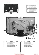
Remove the rear cover fixing screws indicated and then
carefully pull the ‘Rear Cover’ away from the back of the
TV set.
Screw Part number(s) and Description(s)
1) 2-580-640-01 SCREW, +BVTP2 4X16 (32” = 10pcs, 40” = 8pcs)
2) 7-685-648-79 SCREW, +BVTP 3X12 (32/40” = 2pcs)
3) 2-580-595-01 SCREW, +PSW M3X12 (32” = 2pcs)
4) 4-159-298-01 SCREW, +PSW M4X10 (40” = 4pcs)
1
1
=>
1
=>
=>
2
=>
2
3/4
2-1. Rear Cover Removal
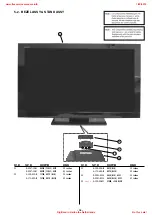
2-2. Stand Assy Removal
Remove the 4 stand fixing screws indicated and lift the TV set
up and away from the ‘Stand Assy’.
Screw Part number(s) and Description(s)
2-580-608-01 SCREW, +PSW M5X16
=>=>
=>
=>
2-4. Loudspeaker Removal
2-3. Speaker Bracket Removal
To remove the ‘Loudspeaker’ first disconnect the
loudspeaker connectors and then remove the 2 screws
circled. Finally gently pull the ‘Loudspeaker’ out of the
speaker bracket.
Screws
To remove the ‘Speaker Bracket’ remove the 1 screw
circled. Then gently pull the ‘Speaker Bracket’ away from
the back of the TV set.
Screw
=>
1/4
=>
1/4
=>
3/4
1
=>
www.freeservicemanuals.info
1/20/2019
Digitized in Heiloo the Netherlands
Not for sale!


