

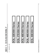

KDL-
32/37/40/46/55EX
500
Series
(A
EP/UK
)
AZ1-L
CHASSIS
Segment: 3a-1
SERVICE MANUAL
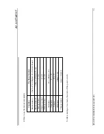
HISTORY INFORMATION FOR THE FOLLOWING MANUAL:
ORIGINAL
MANUAL
ISSUE D
A
TE: 1/
2010
Version
D
ate
S
ubject
1.0
1/2010
No revisions or updates a
re appli
cabl
e at this ti
me.
2.0
2/2010
Amend 32”
(P
.42)
& 37”
(P.45)
EX504 ‘BAL’
boa
rd part number.
3.0
5/2010
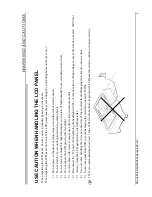
Add update
d Panel Caution Note
(P.6)
.
Add Inverte
r and Tcon Board Part Num
b
ers
(P.42,45,48,51,54)
.
Add illustration showing
location of
neck to base screws
(P.43,46,49,52,55)
.
Add ‘Support, Panel’
Part Num
b
ers
(P.41,44,47,50,53)
.
4.0
6/2010
Add ‘Hotel Assy’
to Exploded Vie
w
s
(P.41,44,47,50,53)
.
Add ‘Hotel Addendum
’
for B2B Models
(P.59)
.
LCD
Digita
l Color TV
9-888-265-04


