TVP-21
23
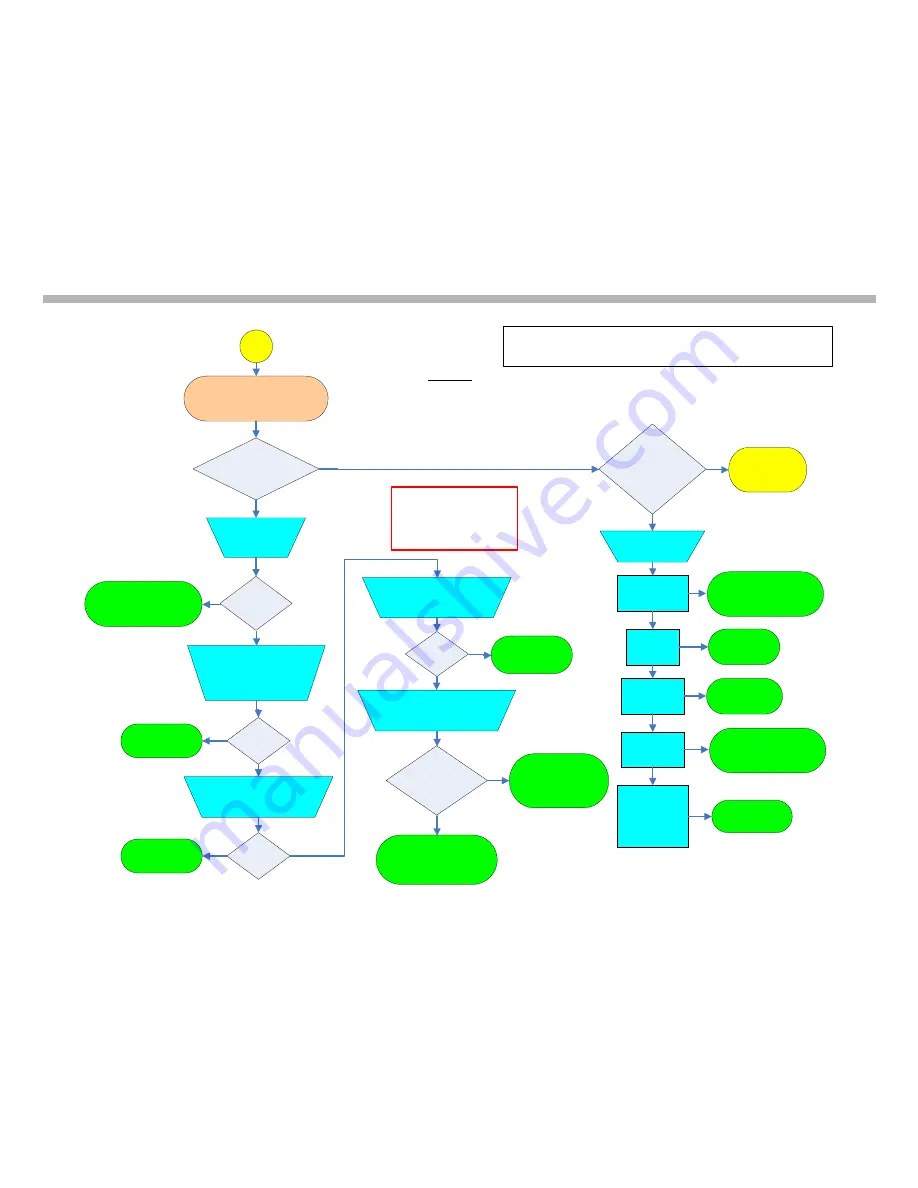
Troubleshooting Flowcharts
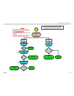
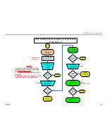
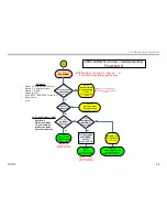
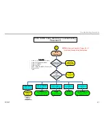
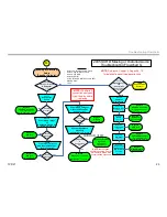
2005 SXRD Missing or Distorted Audio
Troubleshooting Flowchart G
Is Audio
Present?
Check
Audio Output
Var/Fix
No
Missing or Distorted
Audio
(Speaker Outputs)
Is Audio
Missing or Distorted
on
All Inputs
?
1,2, ---,i-Link.
No
Yes
NOTE:
Confirm all
connections between
circuit boards before
replacing
Check
Individual
Audio Inputs
Check
External Devices
and
Connections
Swap Devices and
connections
No Audio
Inputs 1, 3, 4 or 5
**ONLY**
No Audio
Input 2
**ONLY**
Replace
H3-Board
A-1123-102-A
No Audio
Inputs 6 & 7
**ONLY**
No Audio
NTSC Tuner,
ATSC Tuner,
Memory Stick,
or i-Link
**ONLY**
Replace
Q-Box Module
A-1058-689-A
No Audio
Sub-Tuner
**ONLY**
TV OK
Repair External
Devices or
Connections
Good
Bad
Yes
G
Check
Power Supply voltage at
G-Board CN6408/pin 1
“Before Shutdown”
Replace
PD-Board
A-1152-716-A
Replace
ASU/DSU Assembly
Go to Appendix for
Part # Table A-1 & A-2
All Inputs :
Audio 1,2,3 (Composite & S-Video)
Audio 4, 5 (Component Video)
Audio 6, 7 (HDMI)
Audio 8 (PC IN)
ATSC, NTSC, SUB-NTSC Tuners (RF)
Memory Stick
i-Link
Is 14V
Present?
Replace
G-Board
A-1138-898-A
No
Yes
Check
Speaker Resistance
CN3003 &
Connections
on K-Board
10.6 ohms
&
Connections
OK?
Replace
K-Board
A-1138-895-A
or
AK-Board
A-1123-095-A
No
Repair or Replace
Speakers
1-826-236-11
1-826-237-11
Check
Power Supply voltage
at
ASU-Board CN1/pin 10
“Before Shutdown”
Is 3.3V
Present?
Replace
G-Board
A-1138-898-A
No
Yes
Yes
Replace
ASU/DSU Assembly
Go to Appendix for
Part # Tables A-1 & A-2
Replace
ASU/DSU Assembly
Go to Appendix for
Part # Tables A-1 & A-2
Check
Power Supply voltage at
ASU-Board CN501/pin 1
“Before Shutdown”
Is 6.5V
Present?
Replace
G-Board
A-1138-898-A
No
Yes
CN3003/pins 1 & 2 = 10.6 ohm
CN3003/pins 3 & 4 = 10.6 ohm
NOTE:
Reference Chapter 6, Pages 68 - 70
for detailed flowchart step descriptions
NOTE: There are two
speakers per side. The two
part numbers shown here
are for the two speakers.
Summary of Contents for KDS-R60XBR1 - 60" Rear Projection TV
Page 1: ...Models KDS R50XBR1 KDS R60XBR1 Diagnostics and Troubleshooting Course TVP 21 Training Manual ...
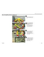
Page 49: ...TVP 21 46 Disassembly Procedures Wire Routing Diagrams Wire Routing Diagrams ...
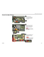
Page 50: ...TVP 21 47 Disassembly Procedures Wire Routing Diagrams cont ...
Page 51: ...TVP 21 48 Disassembly Procedures Wire Routing Diagrams cont ...
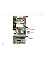
Page 52: ...TVP 21 49 Disassembly Procedures Wire Routing Diagrams cont ...
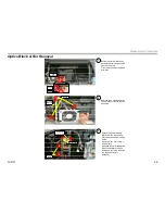
Page 53: ...TVP 21 50 Disassembly Procedures Wire Routing Diagrams cont ...
Page 58: ...TVP 21 55 Chapter 2 Initial Contact Analysis ...
Page 72: ...TVP 21 69 4 Protection Circuits Troubleshooting Flowcharts Flowchart C 1 Figure 4 2 ...
Page 73: ...TVP 21 70 4 Protection Circuits Flowchart C 2 Figure 4 3 ...
Page 74: ...TVP 21 71 4 Protection Circuits Flowchart C 3 Figure 4 4 ...
Page 75: ...TVP 21 72 4 Protection Circuits Flowchart C 4 Figure 4 5 ...
Page 88: ...TVP 21 85 5 Video Processing System Video Distortion Flowchart E Figure 5 3 ...
Page 89: ...TVP 21 86 5 Video Processing System Optical Block Flowchart F Figure 5 4 ...
Page 98: ...TVP 21 95 6 Audio Processing System Troubleshooting Flowchart ...
Page 102: ...TVP 21 99 Appendix 2005 SXRD Service Mode Options ...


