TVP-21
66
4. Protection Circuits
Overall System Description
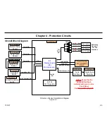
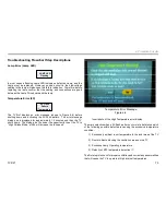
Reference Figure 4-1
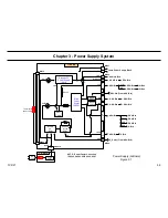
The protection circuits (aka. self-diagnostics routines) for the 2005
SXRD monitor the following circuits and conditions in and around the TV
for abnormalities. If a failure occurs the Green Standby/Power LED on
the front panel will flash a unique pattern depending on the failure that
occurred.
•
Lamp Operating Condition (Lamp Red LED Continuous Flash
Pattern)
•
External Temperature (2X Red Power/Standby LED Flash
Pattern)
•
Internal Temperature (2X Red Power/Standby LED Flash
Pattern)
•
Lamp Temperature (2X Red Power/Standby LED Flash
Pattern)
•
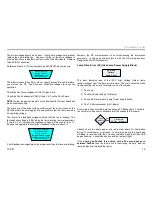
Lamp Door Position (3X Red Power/Standby LED Flash
Pattern)
•
Lamp Plug Position (3X Red Power/Standby LED Flash
Pattern)
•
Fan Rotation (4X Red Power/Standby LED Flash Pattern)
•
Lamp High Voltage (5X Red Power/Standby LED Flash
Pattern)
•
Power Supply and Regulator Output Conditions (6X Red
Power/Standby LED Flash Pattern)
•
Audio Output Circuit Condition (7X Red Power/Standby LED
Flash Pattern)
•
Device Acknowledgement (9X Red Power/Standby LED Flash
Pattern)
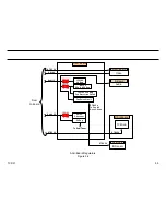
The Display Engine (DE) microprocessor monitors all protection circuits.
The DE microprocessor employs eight unique Green Standby/Power
LED flash patterns to identify one or more of the circuit failures listed in
the previous bullet list. Notice that in some cases the same flash pattern
will occur for different failures, in these cases, you will apply further
troubleshooting procedures to identify the exact area of the failure.
Protection Circuits Functional Description
NOTES: The titles for the protection circuits in this section are those used
in the unit specific Service manual, excepts for those indicated, which are
not listed in the service manual.
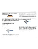
Lamp Error (Continuous Lamp Red LED Flash)
A current sensing circuit mounted on the Lamp Driver Module (or Lamp
Power Supply Block) monitors the current drawn by the Lamp. As the
lamp ages the
current it draw gradually decreases
, and once it falls
below a predetermine threshold or stops completely the protection circuit
detects a defective Lamp. The TV will shutdown and the Lamp LED
flashes continuously.
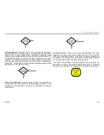
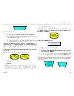
Temperature Error (2X Red Power/Standby Flash Pattern)
The temperature error protection circuit monitors three areas for an
excessive temperature conditions.
The
S1-Borad
(LM75 Temperature Detect IC) monitors the
local external
ambient room
(or Air) temperature. The DE microprocessor regularly
queries IC7100 on the S1-Board over the I2C bus for temperature
information. The threshold is set to approximately 45 degrees Celsius.
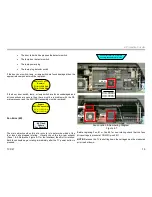
The S1-Board is located in the lower right rear corner of the unit on the
ASU-Board shield when looking at the unit from the rear.
The
S2-Board
(LM75 Temperature Detect IC) monitors the
temperature
Summary of Contents for KDS-R60XBR1 - 60" Rear Projection TV
Page 1: ...Models KDS R50XBR1 KDS R60XBR1 Diagnostics and Troubleshooting Course TVP 21 Training Manual ...
Page 49: ...TVP 21 46 Disassembly Procedures Wire Routing Diagrams Wire Routing Diagrams ...
Page 50: ...TVP 21 47 Disassembly Procedures Wire Routing Diagrams cont ...
Page 51: ...TVP 21 48 Disassembly Procedures Wire Routing Diagrams cont ...
Page 52: ...TVP 21 49 Disassembly Procedures Wire Routing Diagrams cont ...
Page 53: ...TVP 21 50 Disassembly Procedures Wire Routing Diagrams cont ...
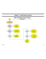
Page 58: ...TVP 21 55 Chapter 2 Initial Contact Analysis ...
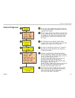
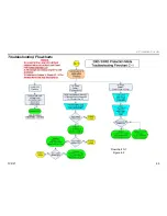
Page 72: ...TVP 21 69 4 Protection Circuits Troubleshooting Flowcharts Flowchart C 1 Figure 4 2 ...
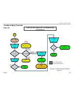
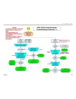
Page 73: ...TVP 21 70 4 Protection Circuits Flowchart C 2 Figure 4 3 ...
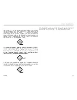
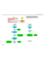
Page 74: ...TVP 21 71 4 Protection Circuits Flowchart C 3 Figure 4 4 ...
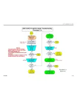
Page 75: ...TVP 21 72 4 Protection Circuits Flowchart C 4 Figure 4 5 ...
Page 88: ...TVP 21 85 5 Video Processing System Video Distortion Flowchart E Figure 5 3 ...
Page 89: ...TVP 21 86 5 Video Processing System Optical Block Flowchart F Figure 5 4 ...
Page 98: ...TVP 21 95 6 Audio Processing System Troubleshooting Flowchart ...
Page 102: ...TVP 21 99 Appendix 2005 SXRD Service Mode Options ...

