TVP-21
78
4. Protection Circuits
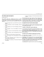
Audio Output Error (7X)
7X Flash
Pattern
(Audio Output)
This error is relatively straightforward. The error occurs when one of the
audio outputs is shorted or if a DC voltage level is present. In either case
the problem exists on the audio board (K-Board).
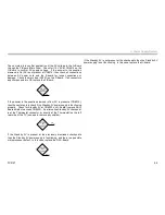
Remove
K-Board
Remove the K-Board to verify that the K-Board is causing the TV to
shutdown (7X).
If the K-Board is defective, the TV will turn on with video and no audio.
If the TV still shuts down (7X), then the problem is with the DE
microprocessor, and consequently, the ASU/DSU assembly must be
replaced.
Panel Error (9X)
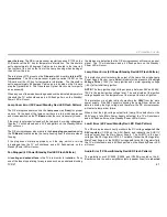
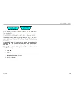
9X Flash Pattern
Microprocessor I2C
Communications error
This error is somewhat deceiving because of the name Panel Error. An
actual defect LCD display will not cause this error or any error for that
matter. The likely reason for the name Panel Error is that a defective C-
Board, which is the LCD display driver can cause a (9X) error. The S1-
Board and the S2-Board can also cause a (9X) error.
The fundamental defect that causes this error is a loss of I2C
communications (or Inter-IC Acknowledgement) between the C-Board,
S1-Board, or S2-Board and the DE microprocessor. One or more of
these three boards have failure to communicate (or acknowledge) the
De microprocessor. Therefore, the fist step in solving the problem is to
check for loose or damaged connections between all three boards and
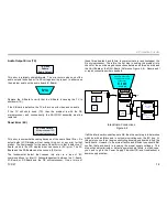
the ASU-Board or the DSU-Board (Reference Figure 4-8). Secure and/
or repair connections where needed.
Check & Secure the
following Inter-board
connections
S1 to ASU
S2 to ASU
C to DSU
If all the inter-board connections are OK, then the next step is to determine
which board has failure and is not communicating over the I2C bus. At
this point you could just begin substituting known good boards to find the
faulty board. However, to be more effective and efficient you should first
confirm that each board is receiving the proper supply voltages. This
step will quickly eliminate or detect a power supply failure, in which case,
you need to go to the Power Supply Flowchart (B) and troubleshoot a
power supply problem.
Inter-Board Connections
Figure 4-8
C-Board
ROOK
DSU-Board
TV
Micro
WE
Micro
IFP
ASU-Board
DE
Micro
Lamp Thermal
Sensor
S2-Board
Ambient Thermal
Sensor
S1-Board
CN7956
CN6901
CN7100
CN7120
CN2303
Microprocessor Power Supplies & I2C
Communications Diagram
4
/
6
6.5V
7
&
11
5V
5V
5V
CN2303
CN6900
I2C
I2C
Summary of Contents for KDS-R60XBR1 - 60" Rear Projection TV
Page 1: ...Models KDS R50XBR1 KDS R60XBR1 Diagnostics and Troubleshooting Course TVP 21 Training Manual ...
Page 49: ...TVP 21 46 Disassembly Procedures Wire Routing Diagrams Wire Routing Diagrams ...
Page 50: ...TVP 21 47 Disassembly Procedures Wire Routing Diagrams cont ...
Page 51: ...TVP 21 48 Disassembly Procedures Wire Routing Diagrams cont ...
Page 52: ...TVP 21 49 Disassembly Procedures Wire Routing Diagrams cont ...
Page 53: ...TVP 21 50 Disassembly Procedures Wire Routing Diagrams cont ...
Page 58: ...TVP 21 55 Chapter 2 Initial Contact Analysis ...
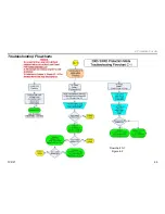
Page 72: ...TVP 21 69 4 Protection Circuits Troubleshooting Flowcharts Flowchart C 1 Figure 4 2 ...
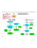
Page 73: ...TVP 21 70 4 Protection Circuits Flowchart C 2 Figure 4 3 ...
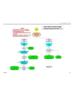
Page 74: ...TVP 21 71 4 Protection Circuits Flowchart C 3 Figure 4 4 ...
Page 75: ...TVP 21 72 4 Protection Circuits Flowchart C 4 Figure 4 5 ...
Page 88: ...TVP 21 85 5 Video Processing System Video Distortion Flowchart E Figure 5 3 ...
Page 89: ...TVP 21 86 5 Video Processing System Optical Block Flowchart F Figure 5 4 ...
Page 98: ...TVP 21 95 6 Audio Processing System Troubleshooting Flowchart ...
Page 102: ...TVP 21 99 Appendix 2005 SXRD Service Mode Options ...

