TVP-21
88
5. Video Processing System
Yes
Can
any
OSD
be
Displayed?
No
Can
User Menu or
QM OSD
be
Displayed?
No
Yes
On-Screen Displays (OSD)
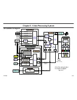
Reference Figure 5-5
•
User Menu
•
QM Service Mode
•
TV Service Mode
•
WE Service Mode
•
Panel Service Mode (DE Microprocessor)
For a detailed diagram showing the location of each OSD generator
reference Figure 5-5. The various OSD’s are very usefully in
troubleshooting a video problem. As shown in the diagram the video
system can be divided into four areas or boards (ASU-Board, DSU-
Board, Q-Box, and C-Board), by verifying that the particular OSD can be
displayed. For example, if the ATI Service Mode OSD were the only OSD
missing (all other OSD’s are OK) then this would point to a defective Q-
Box module.
Another important OSD test is to attempt to display the ROOK test
patterns. Note that the ROOK is located on the C-board, and therefore,
is at the end of the video path just before the Optical Block (the C-board
is part of the Optical Block). Consequently, if the ROOK test patterns can
be displayed then this effectively indicates that the Optical Block is OK
and the defective exists in the circuits before the Optical Block (e.g. the
ASU/DSU Assembly).
If no OSD’s are displayed then you should go to the Optical Block
Troubleshooting Flowchart F next will be discussed in an upcoming
flowchart description section.
If some OSD’s can be displayed then depending on what OSD’s are
displayed will determine the defective area. As previously mention check
the User Menu, which is developed in the Q-Box module, to determine if
the defect is in the Q-Box module or in the ASU/DSU Assembly.
Summary of Contents for KDS-R60XBR1 - 60" Rear Projection TV
Page 1: ...Models KDS R50XBR1 KDS R60XBR1 Diagnostics and Troubleshooting Course TVP 21 Training Manual ...
Page 49: ...TVP 21 46 Disassembly Procedures Wire Routing Diagrams Wire Routing Diagrams ...
Page 50: ...TVP 21 47 Disassembly Procedures Wire Routing Diagrams cont ...
Page 51: ...TVP 21 48 Disassembly Procedures Wire Routing Diagrams cont ...
Page 52: ...TVP 21 49 Disassembly Procedures Wire Routing Diagrams cont ...
Page 53: ...TVP 21 50 Disassembly Procedures Wire Routing Diagrams cont ...
Page 58: ...TVP 21 55 Chapter 2 Initial Contact Analysis ...
Page 72: ...TVP 21 69 4 Protection Circuits Troubleshooting Flowcharts Flowchart C 1 Figure 4 2 ...
Page 73: ...TVP 21 70 4 Protection Circuits Flowchart C 2 Figure 4 3 ...
Page 74: ...TVP 21 71 4 Protection Circuits Flowchart C 3 Figure 4 4 ...
Page 75: ...TVP 21 72 4 Protection Circuits Flowchart C 4 Figure 4 5 ...
Page 88: ...TVP 21 85 5 Video Processing System Video Distortion Flowchart E Figure 5 3 ...
Page 89: ...TVP 21 86 5 Video Processing System Optical Block Flowchart F Figure 5 4 ...
Page 98: ...TVP 21 95 6 Audio Processing System Troubleshooting Flowchart ...
Page 102: ...TVP 21 99 Appendix 2005 SXRD Service Mode Options ...

