26
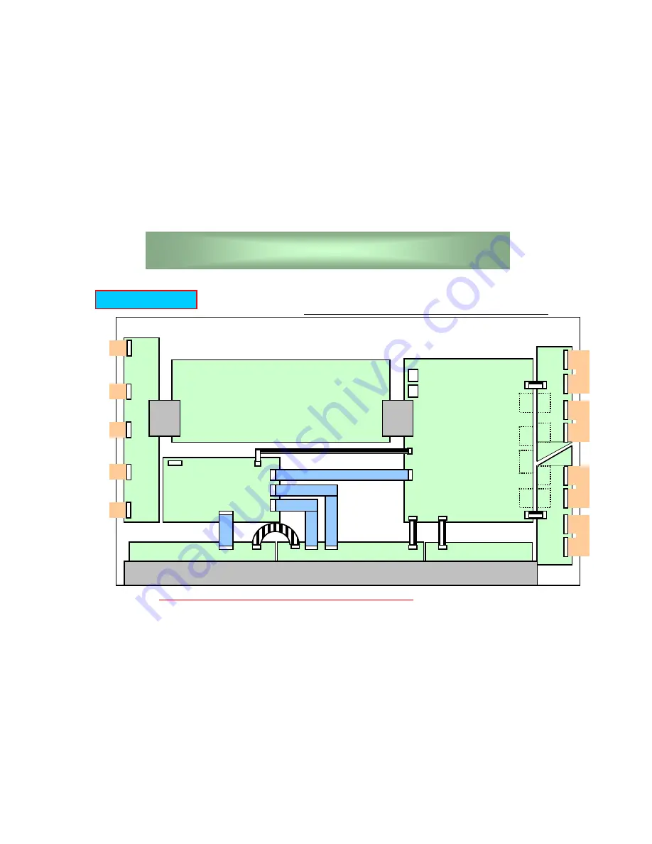
High Voltage Board
6 connectors
Com
m
on
Rel
a
y Board
5 c
onne
ct
or
s
Digital Board
6 connectors
Sc
an Rela
y Boar
d(
Up)
5 c
onne
ct
or
s
Common Bypass Board
Data Relay Board
(Left) 10 connectors
Data Relay Board
(Right) 7 connectors
Sc
an Rela
y Boar
d(
Do
w
n)
5 c
onne
ct
or
s
Check the Cables or Connectors whether connected and locked, or not.
Connectors Condition
We would like you to be careful to handle the modules at assembling.
Data Relay Board
(Center) 12 connectors
Connectors
Summary of Contents for KE-MR50M1 CH
Page 3: ...1 PDP NP series Confirmation Common Manual Ver 1 ...
Page 23: ...21 PDP NP50C3MF01 Confirmation Manual Ver 1 ...
Page 35: ...33 Tester Checking 5 Parts Location High Voltage Board PH2203F ...
Page 38: ...36 Strip Defect 1 Compare with specification 1 strip 2 strip 2 strip Strip Defect ...
Page 39: ...37 Strip Defect 2 3 strip 3 strip 3 strip Strip Defect ...
Page 47: ...45 PDP NP50C3MF01 Repair Manual Ver 1 ...
Page 68: ...Sony EMCS Corporation Ichinomiya TEC 9 878 234 01 English 2004DL08 Data Made in Japan 2004 4 ...


